


In plating today, we get caught up in the latest process, power supply, or new environmental technology.
We tend to set aside one of the essentials: the thing that holds the parts in the tank. The original article was contributed to the Update series by Fred Buzz Schultz. He begins with a foreword, Racks should be treated as important tools of the trade by showing proper consideration for design parameters and maintenance requirements, and goes on:
From a simple copper wire to a complex electromechanical structure weighing a ton or more, a plating rack by definition is a fixture designed to hold, suspend, and, for our purposes, efficiently conduct current to one or more parts in a plating bath.
Just as in the chemical aspect of electroplating, rack problems have been addressed by various sources. And, if necessity is the ‘mother of invention,’ in electroplating, Rube Goldberg might well be the father. The design and construction of plating racks requires a blend of art, craft, technology, and innovation; however, rack care and handling are largely a matter of down-to-earth common sense.
Although the chemistry, electronics, and procedures involved in cost-efficient electroplating receive much of the attention and editorial space in industry trade publications, the plating rack is at the heart of it all. It provides the leading edge at the point where everything happens and can have a significant impact on the result. Fortunately, great improvements in results and overall effectiveness can be achieved by making simple, unsophisticated adjustments.
Design Considerations
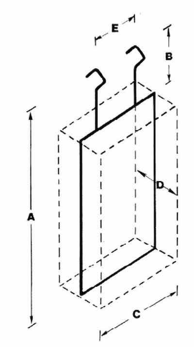 Fig. 1—Dimensional layout of a generic plating rack. Whenever possible, parts should be four in. from the anodes.Any discussion of plating racks should begin with an understanding of the components that make up the essential parts. The hook provides the electrical contact with the cathode bar. The spline supports the parts and carries the current to the all-important work area. Next, the tip makes the actual electrical contact with the parts. Much can be lost if suggestions on maintenance aren’t followed concerning the care and handling of tips. Finally, a rack coating is used to insulate the frame and confine the current to the parts being plated.
Now, let’s examine a few key design parameters. The most important consideration is to be familiar with the type of equipment that the rack will be used with. The rack must be able to fit into the smallest tank on the line.
Like an airline pilot with a preflight checklist, you must establish maximum dimensions, record them in writing, and refer to them for each new rack design. More than anything else, this practice will eliminate costly errors.
Although there are many variations in rack design, the basic types are:
- The single spline rack consists of a vertical central support with tips supporting the work, and is used mainly in hand transfer operations.
- The frame-style rack consists of a box-type frame with tips for work support attached to either vertical or horizontal cross-members. Frame styles can handle almost any size and shape of part and are used on most automatic machines. Machine transfer hoists, loaders/unloaders, and cranes may handle the heavier versions on and off the plating line.
The selection of the appropriate rack can be determined primarily by the limitations of tank space and the nature of the operation, manual or automatic. Important considerations include the dimensions and number of parts per rack, the weight of each part, the total number of required racks, and the electrical current required for the operation.
Regarding rack length, remember to maintain the distance from the bottom of the tank. Sludge, anodes, steam coils, and pipes for air agitation can impede the process. A plastisol coating on the rack could add as much as 0.5 inches to the overall length of the apparatus. In most cases, the work at its highest point should be at least three inches below the level of the process solution. When measuring the rack, we should add 1/4 to 1/2 in., depending on the thickness of the material being employed for the hook or hanger.
The width is a critical dimension in return-type machines because it also represents the direction of travel and must be maintained closely to the manufacturer’s specifications to prevent serious jam-ups and damage to racks and parts.
The number of racks that can be suspended from a cathode bar on any automatic hoist line is determined by the width, shown as C in Fig. 1. Bearing this in mind, it is necessary to check the location of rack hooks along the bar to ensure that they do not interfere with pickup points of the hoist carriage. Although large racks are often used satisfactorily on long bars, they can present problems. They might offer immediate savings, but are difficult to repair and can be out of service for extended periods, thereby reducing productivity. Large racks also require more frequent repairs per unit due to handling problems. In the long run, small racks are generally simpler to use and more cost-effective.
As shown in Fig. 1, thickness D must be less than the distance between the anodes. This is a critical manufacturer-recommended dimension for automatic equipment. In hand operations or with fixed cathode bars, the thickness dimension must be such that the rack can be introduced into the tank between the anode and cathode rods, regardless of the distance between anodes.
Conductivity
The most important function of a rack is to carry current to the workpiece. The rack should be designed to hold the work in a favorable position, allowing solution drainage and gassing during plating.
The outside of the part should be plated as evenly as possible; therefore, the outside surface should be positioned in a plane parallel to and facing the anodes. All parts should be spaced the same distance from the anodes. If the inside surfaces are significant, different techniques such as racking on one side only, staggering parts front and back, or employing auxiliary anodes should be implemented. Racks should also be designed to avoid excessively high local current density on areas of the workpiece. When necessary, a burn bar or current thief can be used to reduce the current density on points or protruding sections. Whenever possible, the workpieces should be positioned to protect one another, thereby saving metal, tank space, current, and the need for frequent replacement of burn bars.
Due to the high amperage requirements for certain types of plating, the current-carrying capacity of the construction material is a crucial consideration. The conductivity of copper is approximately 1000 A/in2 of cross-sectional area [when not in solution]. Steel, however, has a conductivity of just 120 A/in2, and stainless steel about 22 A/in2. Improper material selection or insufficient cross-sectional area can cause a shortage of current delivery to the parts and burn the thin electroless deposits in the case of plated plastics.] Poor selection can also cause excessive heat buildup, resulting in burning and blistering of the rack coating. These, in turn, will result in solution entrapment, dragout contamination, and skip plating. For these reasons, it is essential to consult complete technical information on the materials of construction.
Rack Hooks
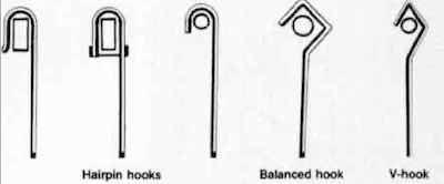 Fig. 2—Types of plating rack hooks.Rack hooks make contact with the cathode bar and are best constructed as a continuation of the spline. This will permit maximum conductivity and strength. However, there are many additional factors involved. For example, is the rack hung on a round, rectangular, or square rod? The balanced hook shown in Fig. 2 is probably the most commonly used and can be formed to fit any rod size. In automatic machines, it is often advantageous to form cathode hooks so that they conform more closely to the exact configuration of the rack carrier.
The important consideration here is the direction of travel. Racks with balanced hooks tend to swing when moving forward, as in hoist lines. The amount of swing depends on several factors such as the length of the rack, speed, and braking action. On rectangular or square bars, hairpin hooks (in the shape of an inverted U) are more efficient. On round bars, bolt hooks are often necessary.
Frame Materials
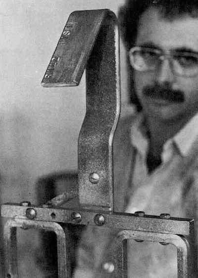 Fig. 3—Stainless steel fasteners are recommended for joining members of copper racks.Because of its excellent conductivity, copper is the most commonly used material for rack frame construction.
Stainless steel and steel are stronger and much more durable, but, as stated, they offer only 3 to 12 percent of the conductivity of copper. Additionally, the increased resistance factor in stainless steel can lead to undesirable overheating of rack components. Although aluminum has better conductivity than steel and often offers desirable weight reductions, it is easily attacked by acids and is soluble in alkalis.
All frame-type racks should be made with a minimum number of joints, maximum rigidity, low electrical resistance, and long life expectancy. Single-piece frames should be constructed, if possible, using horizontal or vertical members. Because high temperatures tend to anneal copper, it is not practical to silver solder the joints. The recommended approach is to make a joint from stainless steel machine screws and nuts, as in Fig. 3. [Rivets are typically used in modern rack construction.] Steel bracing should be used whenever necessary.
The rack should always have enough strength to support its load. Copper is again popular due to its ease of forming and relatively high strength. A hook may be fabricated at the end of the spline or cast separately and attached.
Monel normally is not used due to cost and poor current-carrying capacity, [with one important exception. Today, Monel is the preferred material for racks used in zinc plating.] It has high tensile strength and good corrosion resistance and is used for some auxiliary anodes, particularly in silver solutions. Nickel is used to some extent for special applications where a rack member is exposed to corrosive materials or to reverse-current treatment.
In most cases, flat material for splines gives better ultimate strength in lapped joints. The rack will be more rigid if the flat material is used in long dimensions and in the same plane where the major strain is to be applied.
Contact Materials
Because proprietary strippers employ nitric acid, the majority of racks have stainless steel contacts. Despite its relatively low conductivity, it has not failed to perform satisfactorily in many applications. Recommendations for the number of contacts required are shown in the table. In addition, here are some other guidelines:
- The contacts should not shade a significant area of the part.
- The contacts should not lose tension after repeated loading.
- Spring contacts should be designed so that the bend closes when flexing.
- Sharp points and corners on the part should be oriented to the center of the rack.
- In plating on plastics, areas of the part where contact is made must be properly supported to avoid part distortion. Additionally, placing a contact in a blind hole or deep recess should be avoided, as it may result in burn-off or skip plate.
- Contacts should be sloped back to the frame to prevent dripping on parts below.
- Contacts should not be placed on high-quality surface areas because of the possibility of misplacement or discoloration in the contact area.
In addition to factors such as the type of plating to be performed, the cost of the rack, production requirements, and weight and shape of the part, attaching the contact is another consideration. Rivets can be used to attach contacts, but repairs become more difficult, especially if steel rivets are used and corrosion develops. For this reason, stainless-steel machine screws have become the most common tools for attachment. Their resistance to corrosion makes replacement easier. Plus, it is possible to get a tighter connection than with regular steel. Two bolts are sometimes used to eliminate the possibility of loosening. The addition of 60/40 solder will nearly double the strength and reduce the possibility of twisting and losing electrical contact.
You should also remember that with pressure-type contacts, it is essential to secure the attachments to ensure good electrical contact. Ultimately, it is the evaluation of each application that will determine the most effective method.
Recommendations for Number of Contacts
| Ft2 Plated | No. of Contacts |
| 0 to ¼ | 1 |
| 1/6 to ½ | 2 |
| 1/2 to 1 | 4 |
| 3/4 to 2 | 6 |
| 1-1/2 to 3 | 8 |
| 2-1/2 to 4 | 12 |
| 3 to 6 | 16 |
Rack Coating
Another important requirement in rack design is knowing the limitations of the insulating material to be used. ‘Plastisol’ is short for plasticized polyvinyl chloride resin. It is a 100-percent-solids viscous material and must be cured. All racks should be sandblasted before application of the plastisol. You should also keep in mind that it will not adhere to metal without first applying a special primer.
Insulation on plating racks serves several purposes:
- It conserves metal that otherwise would be plated on the rack and lost.
- It conserves current by confining it only to the parts being plated.
- It permits lighter rack construction because less current is used.
- It improves metal distribution.
- It greatly extends the life of the plating racks.
Proper adhesion and application will vary, depending on the plastisol formulation, the primer, and the procedure. The metal to which the insulation is applied should be clean and free of dirt, grit, scale, or oxides. This practice will permit chemical rack stripping without causing damage to the rack frame materials.
It is sometimes difficult to achieve sufficient coating thicknesses on corners or sharp edges, and special techniques must be used to apply uniform deposits of plastisol to irregular shapes and sizes in certain rack configurations. With this in mind, racks should be designed to facilitate the smooth application of plastisol, free of pits and voids.
Good coating adhesion is also important near the contact point, where a minimal amount of the coating is to be removed. After evaluating the overall design of racks and tips, a method of removing the plastisol from the tip should be selected. [This can involve anything from a knife to a wire brush.]
Summary
Plating racks are expensive tools. If carefully designed and maintained, the original cost may be saved many times in rejects, solution contamination, wasted current and metal, and operator time. If poorly designed and carelessly maintained, they can become very expensive without producing the desired results.
When an expensive plating rack is given a fraction of the care usually lavished on a micrometer, for instance, replacement costs and repairs are greatly reduced. After each run, a group of racks should be checked for required repairs and then hung in a storage area. Tips should be cleaned before they become inoperative. Obsolete racks can frequently be redesigned for a much lower cost than that required for the preparation of new racks.
Do it now; you can take a walk out in the shop right this minute and save money by checking a few things:
- Broken Tips: If there is only one broken tip on a rack designed to hold 10 parts, you’ve lost 10 percent efficiency. Have a predetermined policy on removing racks from service.
- Damaged Coatings: Ruptured coatings at the corners or the bottom of the rack can be costly. Make the repairs now and save the cost of replacing splines.
- Proper Handling: During storage, racks should be suspended on bars to protect the plastisol coating.
- Tip: Plate buildup is an early indicator of potential problems.
- Joints: More joints equal more resistance. Design racks with as few joints as possible to minimize the number of connections.
Donald Swalheim, Ph.D. (1913-1993), worked as a research supervisor for E.I. du Pont de Nemours and Co., Inc., and also worked on the Manhattan Project. He was a member of the AES Branch Education Committee, having previously served as its Chairman, and a former member of the AES Technical Education Board.