


Metal finishing for automotive applications has a century-long history of research and development.
 Dr. James LindsayThrough it all lies a theme, which is all too often easily forgotten. That theme is the interdependency of all the components and process, from substrate to final finish layer. Each element is part of a system - a critical fact that is readily overlooked.
This lecture reviews a number of works in automotive finishing R&D in which understanding of the overall system was absolutely essential to success, from classical nickel-chromium plating to work in vacuum/electroplated hybrids for plated plastics, electrogalvanized zinc and hard chromium in stamping dies.
While the emphasis here is in the automotive area, the underlying philosophy must be considered in all other facets of surface engineering.
Originally published as the 38th William Blum Lecture, presented at the 84th AESF Annual Convention (SUR/FIN 1997) in Detroit, Michigan on June 23, 1997.
The Dangers of Overlooking The Obvious
It has been said, wisely, that "those who ignore history are condemned to repeat it." In the same vein, many concepts in our industry have been known for so long and used so often that they fade into the background, and then into oblivion. To put it bluntly, they become so patently obvious that we forget them.
One area that appears obvious at first glance is the interdependency of all the components and processes in a given application. Each of these elements is part of a system, a critical fact that is readily overlooked. From experiments in the research laboratory to troubleshooting on the production floor, it is all too easy to concentrate on matters at hand, and ignore the total picture.
Metal finishing has been indispensable to the automotive industry during the 20th century. If the century is divided into equal thirds, each period is unique. The first third was the time of the pioneering work, where plating was more of an art than a science. The second period, with the exception of the war years, emphasized the decorative applications. Chromium-plated trim epitomized this era. In the last third of this century, functional applications for wear, corrosion and electronic concerns have grown considerably. Decorative finishes, while no less important, have come to occupy a smaller portion.
Electroplating as Art
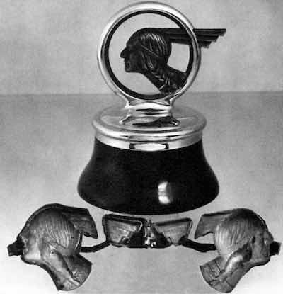 Figure 1 - Radiator cap/hood ornament for a 1930s Pontiac showing the original copper electroform configuration.In the early years of automotive finishing, practice was more art than science. Yet, scientific principles were important. A classic example is a radiator cap/hood ornament from a 1930s vintage Pontiac, shown in Fig. 1. While much of the knowledge germane to its manufacture has been lost with the years, certain facts are known. The ring and cap was a single zinc-based die-casting and was plated with single layers of copper, nickel and chromium. The trademark visage of Chief Pontiac was actually built up by copper electroforming. The electroform consisted of four pieces: The two halves of the head inside the ring and of the stylized headdress outside it. The assembly was completed by brazing, and a final bronze-tint lacquer finish was applied to the Indian head.
Manufacture of this item was no easy task, and could not be accomplished without both manual and technical skills. The plated layers on the die-casting were based on electrochemical principles for both the plating process and corrosion performance. Unique in this example is the electroform. To make it required a knowledge of long-term electrodeposition phenomena and the effects on the physical properties, in particular, deposit stress. The manual skills required in the making of the mold and the removal of the flash and runners, while less scientific, were no less critical. The term "runners" is used here in the sense that they are a path for current flow rather than a path for metal flow, as in metal casting, where the term originates.
Even a venerable application such as this required consideration of the system as a whole. Beyond the physical assembly, the brazing process required compatibility with both the nickel-chromium layers and the copper electroform. In particular, a feel for thermal expansion characteristics of the metals was essential. The finish characteristics had to be maintained, as did the corrosion resistance. Finally, for sake of appearance, the bronzing lacquer had to be applied only to the electroform. That may be obvious, but it is no less important.
Whether such an article could be manufactured in quantity today is subject to conjecture. Certainly, some of the principles are lost to the ages. Yet modern technologies could likely supplant and improve upon what was created, provided that the consequences of manufacture on all components were taken into account.
Decorative Chromium Plating
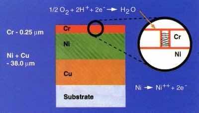 Figure 2 – Schematic layout of nickel-chromium corrosion cell.Decorative chromium plating is synonymous with automotive metal finishing. For many years, it was the mainstay of the metal finishing industry. Most of those who developed the technology are retired or have passed from the scene, but the scheme that they developed is no less sophisticated because of its age.
To the uninitiated, it is surprising to learn that virtually 98% of automotive chromium plating is something other than chromium. It is merely the final, critical layer in a complex multilayer system of electrodeposits. Simply put, we are dealing with successive layers of copper-nickel-chromium or nickel-chromium on steel, zinc die-cast or suitably-prepared plastic substrates.
Typical systems that have performed well in industrial and marine environments are listed here:1
- 38 μm of duplex nickel plus 1.5 μm of microcracked chromium
- 12 μm of copper plus 26 μm of duplex nickel plus 1.5 μm of microcracked chromium
- 38 μm of duplex nickel plus 0.25 μm of microporous chromium
- 12 μm of copper plus 26 μm of duplex nickel plus 0.25 μm of microporous chromium
The primary layers in determining corrosion performance are nickel and chromium. These metals constitute a sacrificial corrosion cell that delays penetration to the substrate. Anodic to the chromium, the nickel corrodes. Manipulation of the structure and properties of these layers led to major improvements in appearance and performance.
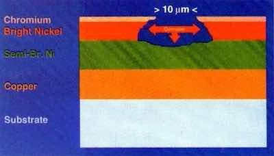 Figure 3 – Corrosion path in a dual nickel system.The thin chromium deposit provides the final appearance and determines corrosion distribution. When deposited from hexavalent solution, chromium forms with relatively low cathodic efficiency, and copious amounts of hydrogen are generated during the process. This leads to the formation of cracks during the deposition. While there have been many refinements over the years, a network of cracks, pores or microdiscontinuities has been the essence of chromium's function. From a visual standpoint, this microscopic network of artifacts imparts an appealing bluish haze to the chromium finish. This is the reason for its use in automotive styling. From a corrosion standpoint, the density and distribution of these discontinuities determine the dispersion of the corrosion current.
As seen in the schematic of Fig. 2, the cathodic area of exposed chromium is much larger than the anodic area of nickel that is exposed through the network of discontinuities in the chromium. The ease of access to the atmosphere puts the system under cathodic control. In the limit, if there is one pore in the chromium, the corrosion current established by the cathode area is channeled into that one pore and rapid penetration into the nickel would obtain. On the other hand, if the network is widely dispersed, the corrosion current is dispersed and distributed so as to minimize local penetration. The inevitable is delayed.
Various methods were employed to optimize this network, including plating dual layers of chromium, codepositing particulate "stress risers" in the final layer of underlying nickel and other manipulations of the chromium deposit. As environmental concerns led to the development of trivalent chromium processes, the issues of maintaining the discontinuity network and the finish color were successfully accomplished.2
The brightness of the chromium depends on the surface of the nickel underneath. In the early years, a single layer of nickel, mechanically buffed and polished to obtain a bright finish, was the norm. This was followed by the development of bright nickel processes, which eliminated costly mechanical finishing. The deposits contained 0.03-0.05% sulfur, derived from the organic brighteners in the electrolyte.
The discovery of organic additives to produce sulfur-free, semibright deposits further increased corrosion life. Utilizing the potential difference between the two, plating a layer of bright nickel atop one of semibright nickel directed the corrosion path laterally, as shown in Fig. 3. The corrosion vector toward the substrate was considerably reduced and salt spray performance was enhanced.
The role of copper in the corrosion performance of these systems is somewhat ambiguous and has been subject to debate over the years. Depending on which substrate and which nickel system is used, copper has been found to help, or have no effect.3 Bright acid copper solutions, however, have been used to good advantage in leveling and brightening over zinc die-cast and steel. An initial alkaline copper strike is required to clean and seal the substrate before the acid copper.
Beyond the primary functions of each coating layer and its relationship to the others, many other factors have been studied. Numerous works on the effects of plating variables on the structure and properties of electrodeposited copper, nickel and chromium have been important in understanding and improving these multi-layer systems.4
The workings of decorative chromium systems have used rather ingenious means to retard the inevitable corrosion forces. Multilayer nickel systems, coupled with manipulations of microdiscontinuities in the chromium overlayer, have been quite successful. Dependence on interactions between layers is critical to this success. Despite the passage of 50 years, the ingenuity reflected in this technology remains undiminished.
Plated Plastics
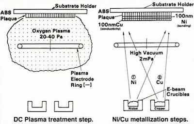 Figure 4 – Schematic representation of the vacuum preplate process for ABS plastics.In the 1960s and 1970s, there was a drive in the auto industry toward weight reduction for fuel economy, which led to the replacement of many zinc die-castings and steel parts with plastics. The primary resin of choice was acrylonitrile-butadiene- styrene (ABS). Its structure was a dispersion of butadiene particles in a matrix of acrylonitrile-styrene. To accommodate customer tastes, the article still required the lustrous metallic appearance provided by decorative chromium plating.
Plating on ABS requires a pretreatment to deposit an adherent, conductive metal, or preplate layer on the polymer. This layer is commonly produced by electroless deposition. The conventional chemical process to do this employs an etch - generally a concentrated solution of chromic acid - to selectively attack the microscopic spheres of butadiene at the surface. This provides a network of sites for mechanical anchoring of the preplate layer to follow. Next, a series of chemical steps produces a network of palladium islands on the etched surface that serve as nucleation sites for electroless deposition. The electroless preplate layer is generally copper or nickel. With this layer in place, the part can be electroplated conventionally with copper-nickel-chromium.
There are many economic, operational and environmental issues attached to this chemical process. It was with this in mind that we undertook a study into alternative preplates. In this work, we decided to incorporate some of the advantages of vacuum deposition technology.
In the perennial debate between the merits of vacuum and chemical processing, one often loses sight of the fact that there are advantages to both. In this work, we developed a hybrid process that used vacuum deposition to provide the pretreatment layer and conventional electroplating for the decorative copper-nickel-chromium. In this way, the environmental concerns of the chemical preplate were addressed, while the unique properties and faster deposition rates of electroplating were retained. As work progressed, the importance of the system perspective was quite evident.
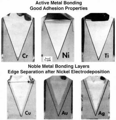 Figure 5 - Response of various bonding laser materials to subsequent electroplating.A two-phased vacuum process replaced the chemical preplate procedure.5 As shown in Fig. 4, the first phase exposed the ABS surface to a direct-current glow discharge oxygen plasma. Analogous to the chromic acid etch, this step enriched the surface with oxygen, which was confirmed by electron spectroscopy. The second phase, vacuum metallization replaced the electroless plating with: (1) 1000 Å of nickel to provide chemical bonding and (2) 1000 Å of copper for electrical conductivity. The metals were sequentially deposited without breaking vacuum, to avoid nickel passivation, and the concept was successful. Adhesion values were obtained that were comparable to those for the conventional process. Although electron-beam metallization was used in our work, newer high-rate methods, such as magnetron sputtering and cathode-arc deposition would be usable today.
The choice of the metal for chemical bonding required an analysis of the entire multilayer system.5 Although the preplate layer might adhere to the plastic, survival of that bond through the remainder of the plating processes was by no means assured. As shown in Fig. 5, different candidate metals responded in different ways. Patterned plating was a design alternative. Using a mask to pattern the deposit, we were able to discern effects at an exposed interface. Certain active metals, such as nickel or chromium, performed well.
Electron spectroscopy indicated that a metal-oxygen-polymer bond had formed. Adhesion was maintained and the interface did not degrade during plating, as indicated by the whitened zone to the original interface line. The whitening indicates tearing (i.e., separation) within the plastic film and not between metal and plastic - the desired result. Other very active metals, such as aluminum, bonded, but tended to passivate upon exposure to the atmosphere. The 1000 Å of copper was a weak barrier to atmospheric diffusion, and strong oxide formers, such as aluminum, readily passivated. Separation then occurred between the bonding layer and the vacuum deposited copper. More noble metals, such as copper, silver or gold, failed differently. While adhesion was maintained through the copper plating process, interfacial attack occurred during nickel deposition. At the nickel plating potential, the tendency was to break the chemical bond and cause separation inward from the original interface. The darker zone noted in the figure indicates a metal-plastic separation.
The process was adequate under laboratory conditions, but at this stage, it was not ready for production. The glow discharge plasma utilized DC current, and was adequate for our carefully-molded, stress-free panels. In production parts, flow and temperature irregularities during injection molding imparted a certain level of stress in the surface. Under these conditions, the relatively flexible butadiene particles worked against the chemical bond. The plating tended to blister in such areas. Again, considering the overall system, it was necessary to make the vacuum process compatible with the vagaries of the molding process. Fortunately, there was an alternative, in the form of a radio-frequency (RF) oxygen plasma. The RF plasma had the ability to physically etch, or sputter, the non-conductive surface. The result was two-fold. The surface was etched, leaving a network of pits for mechanical anchoring of the nickel layer. Further, a relaxation of the stress in the butadiene particles was produced.
One other issue remained. Production plating, on production racks, of our laboratory-preplated moldings resulted in burnoff at the rack contacts. Simply put, the thin vacuum deposit was inadequate to carry the current during the initial stages of copper plating. Starting at a lower current in the first few stations solved that problem, and the parts met all of the specified performance requirements.6
In this work, consideration of the overall system was important. The bonding layer had to survive the electrochemical rigors of the remaining process sequence. The bonding itself had to be augmented with a physical etch to withstand the rigors of molding stresses in the production environment. The current-carrying capacity of the vacuum deposits had to be considered during the first portion of the copper deposit.
Electrogalvanizing
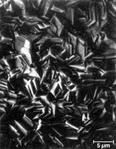 Figure 6 - Surface morphology of a commercial electrogalvanized coating (SEM: 3000×).Since the middle 1980s, the successful introduction and expanding usage of electrogalvanized sheet steel has been the major technological advance in improving quality and product durability in the automotive industry. As was the case with automotive companies and metal finishing suppliers during the development of decorative chromium, the auto and steelmaking industries have cooperated to make a strong commitment to quality with the large-scale application of electrogalvanized steel to automobile body panels. More than a decade of field experience has shown that product durability has been enhanced.
While pure zinc comprises the bulk of the application, zinc alloys - namely zinc-iron and zinc-nickel - have also been developed. These developments have closely paralleled trends in plated coatings for fasteners and small parts, where functional corrosion protection, usually allied with a chromate conversion coating, is the objective. In those areas, zinc-cobalt and tin-zinc have been added to the portfolio.
As the industry has gained knowledge and experience with the use of this material, the importance of a systems approach has been paramount. In this case, consideration must be given not only to interactions between the various elements of the coating process. The entire manufacturing system must be taken into account. The introduction of a layer of electrodeposited zinc into the process of automotive body panel manufacture required changes in perspective. The coated steel is subjected to forming, spot welding, phosphating and electropriming and painting. The zinc deposit must be compatible and remain functional throughout all of this chemical and mechanical mayhem.
In addition to understanding the corrosion behavior of the zinc-coated steels, it was also necessary to learn of their behavior under the various manufacturing operations.7,8 To that end, a research program was undertaken.
At various times, the University of Missouri - Rolla,9,10 the United States Bureau of Mines11 and Bethlehem Steel Company12 joined with us in these efforts. These particular studies were confined to pure zinc deposits electrolyzed from sulfate solutions, using insoluble dimensionally stable anodes. The other successful electrogalvanizing system uses a chloride electrolyte and soluble zinc anodes.
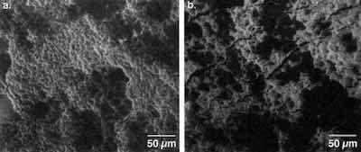 Figure 7 - Response of surfaces to stretch draw forming: (a) basal plane parallel, (b) basal plane near perpendicular (SEM: 1000×).Early on, we noted that the crystal structure and morphology of zinc could be manipulated by adjustment of hydrodynamic and chemical factors - in particular, the pH. The primary character of the surface is a predominance of hexagonal crystal platelets, about 5-10 μm in size and 1-5 μm thick. The platelets are oriented randomly with respect to the plane of the sheet, as shown in Fig. 6. The flat hexagonal faces, in crystallographic terms, are the basal (0001) planes.
A flow cell was built that simulated the conditions of electrogalvanizing (i.e., a strip moving through a solution). The 10 × 20 cm steel cathode was sufficiently large to allow practical measurements of manufacturing behavior. By manipulating the solution pH, we were able to produce deposits with two extremes of crystal orientation:
- Basal planes parallel to the substrate and
- Basal planes nearly perpendicular to the substrate.6†
This allowed the study of the sensitivity of the coating structure to various processing conditions. Considering deformation alone, we expected widely differing behavior in a stamping press.
While the two zinc structures did respond differently to some manufacturing conditions, none of the results was deleterious to the corrosion performance of the material. Most evident was the response to sheet-metal forming.10
To observe the forming behavior, deep draw cup tests were performed, and the resulting surfaces were examined by scanning electron microscopy (SEM). As shown in Fig. 7, under conditions of stretch drawing, the deposit with the basal plane aligned parallel to the sheet underwent grain elongation. The basal plane in this hexagonal system was the slip plane. The ductile deformation occurring led to no fracture or exfoliation. On the other hand, the other deposits, with the slip plane now perpendicular to the direction of stress, cracked.
The other aspect of forming behavior related to drawing friction. A drawbead simulation test was used to determine the coefficient of friction between the die and electrogalvanized surfaces during drawing.11 With the proper die lubricant, the coefficient of friction was 0.11 for both deposits. With a less-efficient light mil oil, not intended for drawing, higher friction was observed for the deposit, with the basal plane oriented parallel to the sheet. More surface galling of the basal-oriented zinc was also noted by SEM, as well as a tendency for this type of zinc to leave particulate zinc on the die surface. Differences existed, but their effects were negated by the use of proper stamping lubricant.
In spot welding, the energy applied to the coating overwhelms any differences arising from crystal structure. The presence of the zinc layer required an adjustment in practices, however.7 Whether hot-dipped or electrogalvanized, zinc-coated steels require higher welding currents and/or longer cycle times than what is required for coated sheet steel. Further, there is a definite tendency for the copper welding electrodes to alloy with the zinc, reducing electrode life. Although the spot-welding process locally removes the zinc coating, this has no significant effect on final product durability under paint.
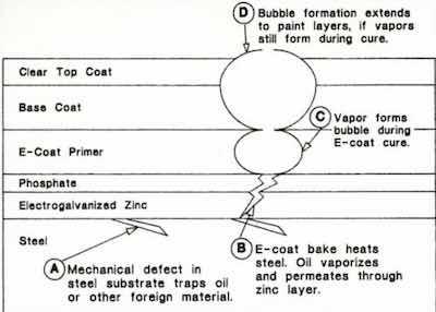 Figure 8 – Schematic diagram of paint rupture phenomenon arising from defects in the steel surface.The first step in the painting process is phosphating, a conversion coating process that establishes a basis for paint adhesion. The aggressive chemistry here also overwhelms any differences arising from crystal structure. Phosphate morphology is unaffected. Still, the phosphate process requires profound alteration with the introduction of the zinc layer. When uncoated steel was the norm, the phosphate solution reacted directly with the iron to form monoclinic zinc iron phosphate (phosphophyllite),‡ which provided an excellent adhesive basis for painting. When the same solution is reacted with zinc-coated steel, a zinc surface is attacked with no iron available, and orthorhombic zinc phosphate (hopeite) is formed.13 This provides good, but not optimum, adhesion. To obtain phosphophyllite structures on zinc, solutions had to be formulated to provide iron from solution rather than from the substrate. Other metals, such as nickel, were also added for further improvement.
After phosphating, the priming layer is applied by electrocoating, which can be loosely described as a polymeric analogy to electroplating. While the zinc deposit structure has no effect here, the presence of zinc does. During the process, a phenomenon called cratering can occur, where an electrolytic discharge causes a momentary local short. The resulting local heat can prematurely cure the forming polymer coat, leaving a defect in the paint that resembles a microscopic crater. The threshold voltage for this discharge is much lower for zinc than for iron. Accordingly, the electrocoating equipment designed to process uncoated steel required some adjustment to avoid cratering.
After the electrocoat process, the remainder of the painting process is relatively unaffected by the presence or absence of the electrogalvanized layer. However, there was one instance of a paint defect which, on analysis, clearly illustrated the interdependence of all of the elements and processes in this system.
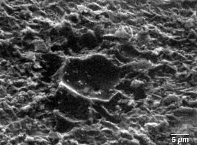 Figure 9 - Rupture site with paint removed (SEM: 1000×)The defect in question was a microscopic rupture in the surface of the final topcoat color finish.8 While in and of itself quite small, on a high-gloss paint finish, its visual effect was far out of proportion to its size. Exhaustive metallographic analysis traced each of these defects down to a flaw in the surface of the steel. During the final rolling and annealing process, an excess of particulates in the lubricating media led to small pits, or pockets in the steel surface, which ultimately trapped some of the lubricating oils. Like a virus, these small sites lay dormant through the electrogalvanizing, forming and phosphating processes. When exposed to the curing temperatures of 160°C for the primer and paint, problems began.
As shown in Fig. 8, the oils vaporized and permeated the zinc and phosphate layers, and the vapors formed a bubble in the curing primer. If there was sufficient oil remaining, the process repeated itself in the color coat layers, forming a volcano-like defect on the surface. The SEM photo of Fig. 9 shows the defect dramatically, where paint layers have been removed with solvent. Nested within the remaining phosphate layer is a crater, which is the lower segment of the bubble formed in the primer layer. The hole in its bottom is the path from the substrate defect.
Each site analyzed could be traced to a defect in the underlying steel. While other causes were offered, including permeated hydrogen evolved during the electrogalvanizing process, this appeared to be the best explanation. When the annealing process was addressed and the source of particulates was eliminated, the condition disappeared. There was no reason to believe that this condition had not occurred when bare steel was the norm. The presence of the zinc, however, made the system more sensitive. We felt that the phosphate reaction on bare steel might have provided a cure early on.
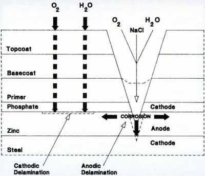 Figure 10 - Schematic diagram of corrosion site in painted electrogalvanized steel.Beyond compatibility with the manufacturing process, zinc still had to perform its intended function: Corrosion resistance via sacrificial protection. As shown in Fig. 10, the corrosion scheme has many similarities to that of decorative chromium. The layer of paint is analogous to the chromium. The organic topcoat remains permeable by hydrogen, and the system is again under cathodic control. The corrosion cell can be established through some weakness in the paint. The most likely scenario is through the formation of a scratch, because the automobile experiences various punishments during its use (careless contact with the door of another car, the impact of a stone chip, vandalism, etc.).
There was interest as to whether the corrosion behavior was sensitive to the crystal orientation of the zinc. In studies on zinc single crystals, it had been found that the anodic corrosion rate was lower on the basal planes than on wall planes.14 From this, we hypothesized that the corrosion path could be directed laterally with zinc oriented with basal planes parallel to the substrate. This scheme would be similar to that accomplished with semibright and bright nickel in the decorative chromium area.
Accordingly, the corrosion behavior of electrogalvanized panels with the basal plane orientation was compared to that for commercial samples with random orientation. To examine the effects of forming, a dome was formed in the center of each panel. After phosphating and painting, a line was scribed into the paint, across the domed area. The specimens were then subjected to a cyclic corrosion test known to correlate well with field test results.15 Depth of corrosion or paint separation in from the scribe was used to evaluate corrosion.
Contrary to expectations, there was no significant difference in corrosion performance between the basal-oriented zinc and the randomly oriented material. Paint delamination was indeed accompanied by anodic dissolution of the zinc. Separation tended to occur at the primer/phosphate interface, however, which in turn opened up the zinc to corrosion from the interface, and not solely from the scribe. Orientation was not a factor in this case.
The use of electrogalvanized steel for automobile body panels required a thorough understanding of all consequences of introducing a layer of zinc between the steel and the paint. Beyond the zinc plating process itself, each step in the manufacturing cycle required analysis and, where needed, some adjustment.
Plating of Stamping Dies for Wear Resistance
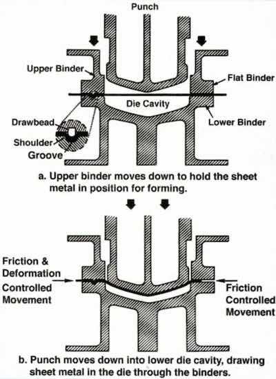 Figure 11 - Essential motions in a doable-action press.Another plating application in the area of automotive body panels relates to the stamping dies themselves. In recent years, the trend has been to hard-chromium-plate the surfaces of stamping dies to minimize wear. The procedure often involves a considerable amount of post-plate finishing to achieve desired stamping dimensions. Experience in stamping plants showed that there was considerable variation in the ability of different chromium-plated dies to form sheet metal.
The basic principles of double-action stamping process are shown in Fig. 11. The upper die half contains two elements: The upper binder and the punch. These are complemented in the lower half by the binder and die cavity, respectively. As the die is closed, the upper binder lowers to the outer rim of the sheet metal blank to hold it in place. The punch continues downward to form the part. During forming, sheet metal is drawn from the binder area into the cavity. The rate of metal flow is controlled by friction. Excessive friction can lead to tearing, while insufficient friction can cause wrinkling. Any chromium plating would have an influence on this friction.
The die friction would be influenced by the surface morphology of the hard chromium. That morphology would in turn be influenced by the original surface condition of the steel substrate. Early work had indicated that differences in friction resulted from different surface finishes.
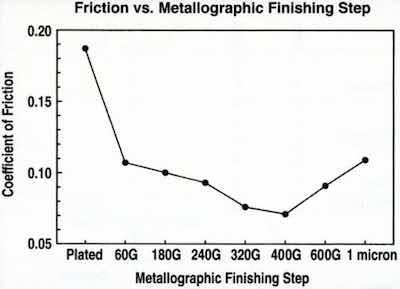 Figure 12 - Drawbead friction between EG steel and chromium-plated die surface at various levels of die surface finish.Using a drawbead simulation test," we measured the coefficient of friction between electrogalvanized steel and chromium-plated die steel, with variations in the surface finish. The surface finish was obtained by grinding and polishing chromium-plated drawbeads to various levels of surface finish. The results are shown in Fig. 12, on monotonic order of finishing particle size. There was an intermediate roughness at which minimum friction is obtained. We also found that the original finish of the die steel had an influence on the final surface roughness of the chromium deposit.
In chromium-plated stamping dies, then, another factor must be taken into account: The final finish is important to proper sizing of the stamping.
Conclusions
Electroplating has found its way into many applications in the automotive industry. In addition to the areas discussed here, functional finishes for fasteners and small parts, and finishing for electronics are also critical applications. In the case of the latter, applications range from wiring harnesses to computers.
In each application, it is essential that the engineer consider the implications on the entire system under study. That system often encompasses more than might be realized at first glance. A shortcoming in the initial phases of surface preparation can have implications far down the line. A change in the steelmaking process and its effect on the final paint finish effectively illustrates this point.
Written by Dr. James Lindsay as the recipient of the 1996 Scientific Achievement Award. Dr. Lindsay worked for many years for General Motors. He holds a master's in materials engineering from Rensselaer Polytechnic Institute, and a Ph.D. in metallurgy from Pennsylvania State University.
References
- G. DiBari, "Nickel Plating," in ASM Handbook Series: Volume 5 - Surface Engineering; 201 (1994).
- D.L. Snyder, "A Comparison of the Corrosion Characteristics of Trivalent and Hexavalent Chromium Electrodeposits, Plating and Surface Finishing, 66 (6), 60 (1979).
- H. Brown, and B.B. Knapp, "Nickel" in Modern Electroplating, F.A. Lowenhein, Ed., Wiley-Interscience, (1974); p. 309.
- F.A. Lowenheim, Electroplating, McGraw-Hill (1978).
- J.H. Lindsay and J. LaSala, "Vacuum Preplate Process for Plating on Acrylonitrile-Butadiene-Styrene (ABS)," Plating and Surface Finishing, 72 (7), 54(1985).
- General Motors Engineering Standard GM-4372,3,4-M (1989).
- J.H. Lindsay, "The Impact of the Zinc Layer on the Manufacture of Automotive Sheet Steel," Proc. Symp. of Zinc-Based Steel Coating Systems: Metallurgy and Performance, TMS, Warrendale, PA (1990); pp. 281-294.
- J.H. Lindsay, "Electrogalvanized Automotive Sheet Steel and the Manufacturing System," Plating and Surface Finishing, 79 (5), 127-135 (1992).
- J.H. Lindsay and T.J. O'Keefe, "Electrogalvanizing," in Modern Aspects of Electrochemistry - No. 26, B.E. Conway, J. O’M. Bockris and R.E. White, Eds., Plenum Pub., New York, NY (1994); pp. 165- 228.
- S.F. Chen, J.S. Cuzmar, T.J. O'Keefe, E.R. Cole, V.R. Miller and J.H. Lindsay, "Measurement of Mass Transfer Effects in Sulfate Electrogalvanizing Electrolyte," Proc. AESF Fifth Continuous Strip Plating Symp., AESF, Orlando, FL (1987).
- J.H. Lindsay, R.F. Paluch, H.D. Nine, V.R. Miller and T.J. O'Keefe, "The Interaction Between Electrogalvanized Zinc Deposit Structure and the Forming Properties of Sheet Steel," Proc. AESF 75th Annual Tech. Conf., AESF, Orlando, FL (1988).
- J.H. Lindsay and C.R. Shastry, "The Effect of Crystal Orientation on the Corrosion Behavior of Electrogalvanized Auto Body Panels," Proc. AESF 80th Annual Tech. Conf., Orlando, FL (1993).
- C.R. Shastry and Townsend, "Mechanisms of Cosmetic Corrosion in Painted Zinc and Zinc Alloy Coated Sheet Steels," Corrosion, 45 (2), 103 (1989)
- D. Abayarathna, E.B. Hale, T.J. O'Keefe, Y-M. Wang and D. Radovic, "Effects of Sample Orientation on the Corrosion of Zinc in Ammonium Sulfate and Sodium Hydroxide Solutions," Corrosion Science, 32 (7), 755 (1991).
- General Motors Engineering Standard GM-9540-P, Method B.
- J.H. Lindsay, M.K. Mickalich and H.D. Nine, "The Effect of Surface Finish on the Drawing Characteristics of Chromium-Plated Sheet Metal Forming Tools," SAE Tech. Pub. No. 910510, in Autobody Stamping Technology Progress, Special Technical Publication SP-865, SAE, Warrendale, PA (1991).