


The process of testing new coatings or approving new suppliers requires a series of tests to control the stability of the process, coating, or the supplier's production capability.
 Lukasz WojtasOften, one of the criteria is microstructure evaluation, which enables us to measure not only the thickness of the coating but also the correctness of its structure. The coating should be free of defects such as porosity, microcracks, incomplete bonding, or interface contamination.
During the metallographic evaluation of a new coating, it is beneficial to correlate the obtained results with those of another laboratory, especially when the microstructure is unsatisfactory, and the results of other tests on this coating are accurate. Why? For thin and soft coatings with a thickness below 100 micrometers and a microhardness below 50 HV 0.01, as shown in Fig. 1, the microstructure is often damaged by incorrect sample preparation. Therefore, it is essential to verify whether the problem lies in the coating or not.
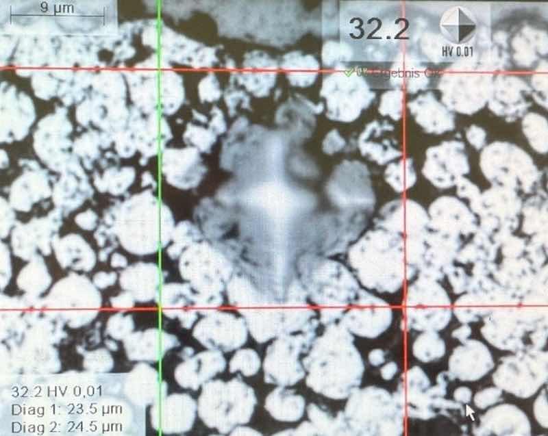 Figure 1: Sacrificial aluminum-ceramic coating with a hardness of 32HV 0,01.
Below, we have compiled some examples to illustrate the mistakes that can be made during sample preparation. We noticed these problems during the sample preparation of some soft coatings evaluated in our MW Coatings Hub laboratory.
Prepare Sample for Metallographic Evaluation
Cutting is the first step required to prepare a sample for metallographic evaluation. An example of problems that may occur during cutting soft coatings, such as the PTFE coating used on gas turbine parts, is burns. During non-destructive testing, the coating met all customer requirements; however, metallographic evaluation was significantly difficult due to coating damage caused by overly aggressive cutting.
Using cooling while cutting parts with thin coatings and large cross-sections of the substrate is not sufficient; it is also necessary to maintain an appropriate cutting speed. Fig. 2 shows a PTFE coating damaged during cutting (it is a coating with a low coefficient of friction for continuous use up to 500°F (260°C).
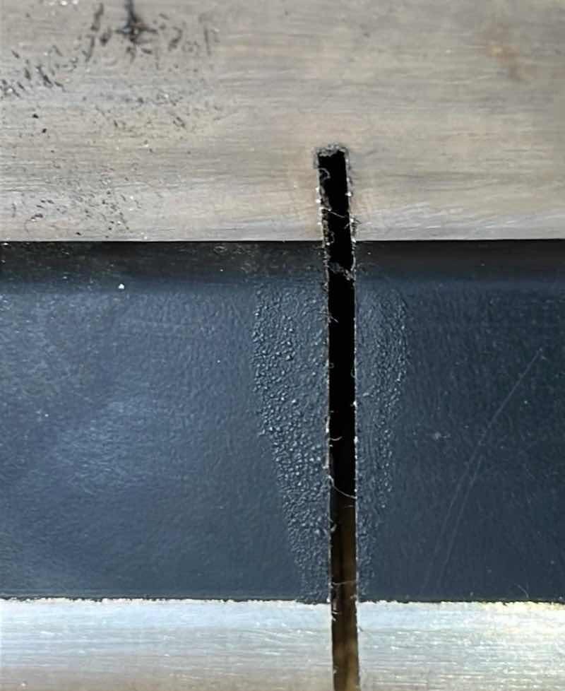 Figure 2: PTFE coating with a low coefficient of friction for continuous use up to 500°F (260°C) - damaged during cutting - burnt and dusty.
The correct microstructure of this coating - Fig. 3, was made on a correctly cut sample. For the sectioning itself, a wide variety of methods can be used, but to meet the demands for a materialographic cut, only very few techniques are feasible. Cutting problems in metallography distort the analysis of a coating microstructure. Common issues include burrs, burning marks, and surface deformation, all of which can be minimized by using appropriate cutting techniques and parameters.
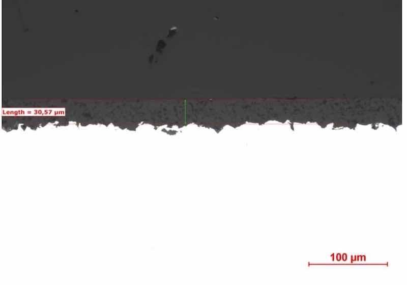 Figure 3: correct microstructure of PTFE coating from Figure 2.
Avoid Problems That Can Negatively Affect Metallographic Evaluation Result
Cutting problems are not the only sample preparation steps that can negatively affect the metallographic evaluation result. A common mistake is using overly aggressive grinding and polishing parameters for samples with soft coatings. Polishing for too long or using too high pressure on the sample with coarse-grained materials can cause chipping or delamination. Fig. 4 shows an aluminum coating that was ground with a pressure of 30 N for 2 minutes on each of several grinding and polishing steps in the opposite direction to the adhesion of the coating to the substrate. This long grinding time and high pressure, typically used for samples with hard materials, such as coatings applied by HVOF, caused tear-offs of the aluminum grains and deep scratches that were very difficult to remove with subsequent grinding and polishing steps.
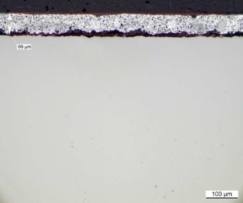 Figure 4: Microstructure of the sacrificial aluminum-ceramic coating with visible imperfections, scratches and decohesion, sample ground with too much pressure, and in the direction opposite to the adhesion of the coating to the base material - incorrectly prepared in an external laboratory.
This gave the misleading impression of a highly porous coating. Changing the parameters, including pressure, time, and gradation of the abrasive paper to a less aggressive one and the direction of grinding, gave a true picture of the same coating, Fig. 5. A common problem in samples where the coating is applied on both sides of the substrate, e.g., leading and trailing edge of the blade or vane - Fig. 6, on this type of samples the decohesion very often appears.
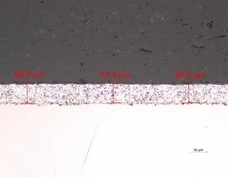 Figure 5: The microstructure of the sacrificial aluminum-ceramic coating from FIGURE 4 prepared by the MW Coatings Hub laboratory using less aggressive grinding and polishing parameters and after rotating the sample in the holder by 180°.
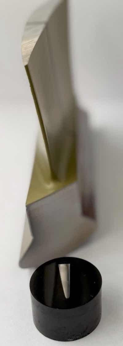 Figure 6: metallography sample from IGT cold section blade – suction and pressure side - prepared at MW Coatings Hub.
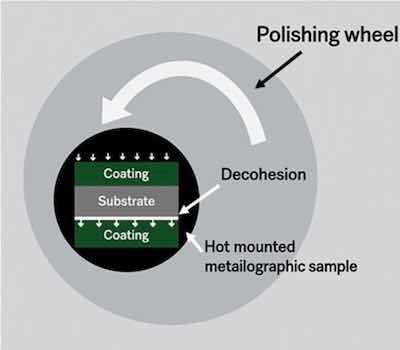 Figure 7: Decohesion formation during grinding/polishing on a double-sided coated sample.The reason for decohesion in this type of sample is shown in Fig. 7, and this is mainly indicated by delamination on one side of the sample. Also, an inspection of proper coating adhesion before the metallographic examination, indicating no delamination problems, may indicate incorrect preparation of the metallographic sample. It is recommended to perform an adhesion test according to EN ISO 2409 before commencing the metallographic evaluation. The lack of visual indications on the coating before cutting, such as pinholes, spalling, chipping, cracking, and other imperfections that could be detrimental to the coating's function, suggests that the coating should not have adhesion problems. If we have samples with coatings applied on both sides of the substrate, like samples from turbine blades where the coating is applied on the suction and pressure side, the evaluations should be performed in two separate steps:
Steps of Evaluation
The first step of evaluation should cover only the side where, due to the grinding direction, the coating was pressed to the substrate because, at the same time, the other side of the sample is subjected to pressure in the opposite direction, resulting from the grinding direction.
The second step in evaluating this type of sample will be to rotate it 180° in the grinder-polisher holder and re-grind, polish, and evaluate the second side.
These are just a few examples of the root cause of the problems identified during the evaluation of the soft coating microstructure, which may consequently lead to an incorrect assessment of the coating quality. Suppose we are unsure about the correctness of the results. In that case, it is advisable to correlate them with those of another laboratory, preferably one with experience in preparing samples with soft coatings. Most laboratories have experience evaluating hard coatings sprayed by APS or HVOF. MW Coatings Hub offers not only professional coating applications but also professional quality evaluation.
Conclusion
Why is correct coating evaluation so important? Because it can save a significant amount of time in analyzing current results and determining the chosen direction of coating development.
An example is the development of the hexavalent-chromium-free sacrificial aluminum coating, whose research goes back many years. If we incorrectly evaluate the coating in any phase of research, it may turn out that the next direction of development we choose will be wrong, and lost time can be very expensive.
Łukasz Wojtaś is the Chief Operations Officer at MWC Hub, a coating application shop for organic and inorganic coatings for the power gen and aerospace industry. Visit https://mwc-hub.com.
References
- J. Iwaszko, K. Kudla, Surface modification of ZrO2-10 wt. % CaO plasma sprayed coating, Bulletin of the Polish Academy of Sciences, 2016
- A. Van der Ven, G. Ceder, The thermodynamics of decohesion, Department of Materials Science and Engineering, Massachusetts Institute of Technology, 2003