
We investigated the electrochemical properties of compounds and chlorides in the films formed on the surfaces of Mg alloys using cavitation for phosphating.
 Masataka Ijiri, Toshihiko Yoshimura, Yasumasa Chino, and Shoichi Kikuch.The compounds formed by this treatment were Mg3(PO4)2 and Mg(OH)2. In addition, electrochemical measurements and combined cycle tests were carried out to investigate the chloride corrosion resistance of the films formed after surface treatment. Regarding the anodic polarization curves, each surface-treated sample exhibited passivation–depassivation behavior. In cathode polarization curves, the corrosion rate for each surface-treated sample was approximately 1/10 that of the corresponding untreated sample.
In the combined cycle test, the amount of surface oxidation caused by chlorides was less for each treated sample than for the corresponding untreated sample. In addition, when droplets containing chlorides were dropped onto a surface and the angle of the droplets that adhered to the surface was measured, the angle for the untreated sample remained constant even after the droplets were dropped several times. However, when several droplets were dropped onto each of the cavitation-treated samples, some areas were highly hydrophobic and some areas were less hydrophobic than the untreated samples.
The results revealed that, although the coating formed on Mg alloys by phosphating using cavitation showed a protective effect in the early stages when chlorides were attached, the protective effect decreased over time.
1. Introduction
In recent years, the automobile industry has promoted the use of electric vehicles to reduce CO2 emissions from internal combustion engines. An electric vehicle requires a battery weighing approximately 500 kg [1] to ensure the same driving range as a vehicle with a conventional internal combustion engine. Reducing the weight of electric vehicles through the use of lightweight metals that are lighter than steel is an effective approach to improving their power performance and driving range.
In particular, Mg has the lowest density of all practical metals and is expected to be a lightweight metallic material [2] for the transportation equipment field. However, in some applications, it exhibits poor durability against chlorides and poor mechanical properties; it is therefore not used in applications that require high performance. By contrast, Mg-based composites are expected to be used in high-performance applications [3,4] because of their low volume density and good mechanical properties. However, Mg-based composites have high manufacturing costs and complicated manufacturing processes [5,6]. Therefore, although the applications of Mg-based composites are limited, the ability to partially or selectively reinforce the surface of Mg-based materials is important because it avoids fabricating entire components from Mg matrix composites. For example, surface engineering efforts are underway to improve the mechanical properties of Mg alloys without substantially adversely affecting the properties of the substrate [7].
Currently, there are various coating technologies for Mg alloys, including laser-beam composite surfacing, electron-beam surface modification [8,9], magnetron sputtering [10,11], plasma spraying [12,13], and atmospheric-pressure nitrogen plasma treatment [14]. However, each of these coating techniques results in a weak interface between the coating and the substrate and requires a vacuum chamber. In addition, the application of such coatings is limited by several major factors, including the extremely slow deposition of ceramic particles, inconvenient operation, and high manufacturing costs. In the case of steels, their electrochemical properties [15,16] are improved by promoting the deposition of shot particles under high temperatures onto their surfaces; however, Mg, like Al, has a low melting point, making this method difficult to use in industrial applications.
Hence, we focused on surface treatments using liquids. One of these treatments, chemical conversion coating, creates a coating by inducing a chemical reaction on the metal surface. The chemicals used in this treatment form a film on the surface of the substrate through various methods (e.g., redox reactions, electrochemical oxidation, and sulfurization). The purpose of this treatment is to improve the corrosion resistance of the metals and the adhesion of paint. It is applied to the surfaces of automobiles, building materials, springs, and other mechanical parts and is used to prepare the surface for painting, to color surfaces, and to prevent rust. Currently available chemical treatments include chromating, phosphating, and blackening. Such treatment methods are less expensive and easier than plating; however, they result in coatings with inferior corrosion resistance because, unlike plating, they do not produce a thick film on the substrate surface. We therefore devised a method to induce cavitation bubbles during the phosphating process to improve not only the corrosion resistance but also the mechanical properties of Mg alloys for practical applications.
Cavitation bubbles are generated in water using ultrasound or water jets, and numerous methods [[17], [18], [19]] have been proposed to generate them. These methods include water-jet peening (WJP) and multifunction cavitation (MFC) [[20], [21], [22]] at high temperatures and pressures. In the MFC process, ultrasonic waves irradiate cavitation bubbles generated when a water jet is ejected into water, at the point where the flow velocity decreases. A feature of this method is that the cavitation bubbles collide with the target object slowly, enabling surface treatment for shapes more complex than simple plates, which was previously difficult [[23], [24], [25], [26]]. In addition, after ultrasound irradiation, the temperature inside the cavitation bubble increases as a result of repeated isothermal expansion and adiabatic compression. In fact, the increase in surface temperature during MFC treatment has been reported to cause age hardening [27,28] in Al alloys and decarburization [29] in steels. In addition, when MFC was used in conjunction with a phosphate treatment, a film was reported [[30], [31], [32]] to form on the surface of Mg alloys and the fatigue properties of the alloys were reported to have improved [33,34], demonstrating the effectiveness of the MFC treatment. This cavitation treatment tends to induce elevated temperatures within the cavitation bubbles, resulting in the formation of a coating with reduced unevenness on the Mg alloy surface and an increase in its thickness compared with a coating formed by treatment with phosphoric acid alone [31]. Studies that elucidate the mechanism of film formation and assess the corrosion resistance to chlorides are expected to provide new insights into potential chemical conversion coatings.
In the present study, we used WJP and MFC as processes to generate cavitation bubbles during phosphating, formed a film on the surface of a Mg alloy, identified the compounds in the film, and evaluated the effect of chlorides on the film.
2. Experimental procedures
2.1. Materials and processing
The test material used in this study was a Mg alloy (Posco Japan, AZ31). Its chemical composition is shown in Table 1. The dimensions of the test sample were 40 mm × 50 mm × 5 mm. All samples were machine polished with emery paper from #80 to #2000 and then mirror polished with a suspension (OP-S Nondry, Struers) on a buffing machine (MD/OP-Chem, Struers). The mirror-polished samples were surface treated in the apparatus shown in Fig. 1. The apparatus was used to generate cavitation bubbles using a water jet in water. In WJP technology, the volume of tap water is changed in a ploughing pump (Maruyama Excel, MW7HP40LX11KW-C37), and high-pressure water is released into the water through an ejector nozzle with a ⌀0.8 mm discharge port. Cavitation bubbles generated by WJP gradually form in places where the saturated vapor pressure in the water decreases. When these bubbles collapse, a high pressure of ∼10,000 atm is transmitted to the surrounding area as an impact. In addition, in MFC, when these cavitation bubbles generated by WJP are irradiated with ultrasound at a frequency of ∼28 kHz while their flow velocity is reduced in water, the bubbles undergo repeated isothermal expansion and adiabatic compression depending on the phase of the sound pressure and reach a temperature of 3000–5000 K [35]. Therefore, the cavitation bubbles generated by MFC have a higher temperature than those generated by WJP. In addition, shock waves generated by WJP are also generated by MFC. In general, vibrations generated by ultrasound in water form cavitation bubbles; the interior of these bubbles reaches a high temperature of several thousand kelvin, inducing the sonoluminescence phenomenon. In fact, in previous research [35], the color temperature of light emitted when bubbles generated by MFC collapse has been estimated using the blackbody radiation energy equation to be approximately 5300 K. In addition, phosphoric acid (H3PO4, Fujifilm Wako Pure Chemical) was added to the ejector nozzle in Fig. 1 at a concentration of 8.87 × 10⁻⁴ mass%; the pH in the water tank after treatment was 6.6–6.9. When the concentration of H3PO4 used during treatment was high, the film formed on the surface after treatment became uneven [31]; the H3PO4 concentration was therefore kept as low as possible. The treatment conditions were as follows: the distance between the ejector nozzle and the sample was 65 mm (standoff distance), the pump injection pressure was 35 MPa, and the treatment time was 5 min. The standoff distance was set at the position [36] where cavitation bubbles were most likely to occur. The ultrasonic processing (Honda Electronics, WD-1200-28 T) conditions used were an ultrasonic output of 800 W and dual mode.
Table 1. Chemical composition of the AZ31 Mg alloy (mass%).
| Al | Mn | Si | Zn | Mg |
| 2.94 | 0.34 | 0.1 | 0.74 | Bal. |
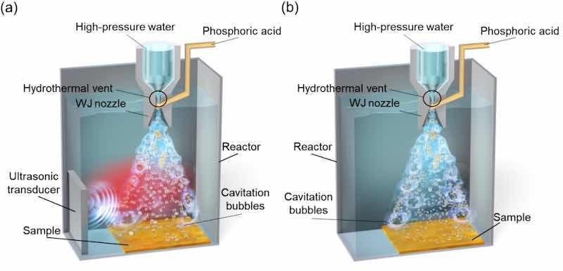
Fig. 1. Schematics of the (a) MFC and (b) WJP processing equipment.
2.2. Evaluation method
Scanning electron microscopy (SEM, JEOL, JSM-IT 500) was used for surface observations. To investigate the chemical bonding state for the coating, we conducted reflectance measurements using a spectrometer. These measurements were performed using a Fourier transform infrared spectrophotometer (Agilent Technologies, 680IR) equipped with an accessory for measuring specular reflectance. The measurement conditions were a wavenumber range from 4000 to 400 cm−1, an accumulation count of 256, and a resolution of 8 cm−1. The measured value was the relative reflectance for an angle θ = 10°, and the reflectance of a Au-coated surface mirror was taken as 100 %.
For the electrochemical measurements, four samples measuring 18 mm × 18 mm were cut from the untreated material and from each cavitation-treated material; these samples were then attached to a holder that regulated the testing area of 1 cm2. The solutions used during the test were Mg(OH)2 and 350 mL of 5 mass% NaCl solution adjusted to pH 9–10; the liquid temperature was 308 K. In addition, the solution was gently stirred with a magnetic stirrer during the test, which was conducted in an open system. Potentiodynamic polarization curves were recorded in the anodic and cathodic directions from the corrosion current after each sample was immersed in the solution for 10 min. The scanning rate was set to 0.2 mV/s. Electrochemical impedance measurements (Ametek, Versastat 3) were carried out with an amplitude of ±5 mV relative to the corrosion potential; the frequency range was 10 kHz to 0.1 Hz. The measurements were conducted for up to 24 h. An analysis with an electrical equivalent circuit was carried out using commercial software (Scribner, ZView).
In addition, a combined cycle test was performed in accordance with JASO standards M609 and 610, with six cycles of salt spray (2 h, 308 K, 5 % NaCl), dry (4 h, 333 K, 20–30 % relative humidity (RH)), and wet (2h,323K,〉95 % RH) conditions (Fig. 2). After the combined cycle test, the samples were cut into 5 mm × 5 mm × 5 mm pieces using a cut-off machine, and the cross sections were observed using a scanning electron microscope equipped with an energy-dispersive X-ray spectrometer (Jeol, JSM-7100F). In addition, the chemical composition of the films in the depth direction was analyzed using a Marcus-type glow-discharge optical emission spectroscopy (GD-OES) surface analyzer (Horiba, GD-Profier2). The measurement conditions were an Ar gas pressure of 600 Pa and a high-frequency output of 35 W. To evaluate the uniformity of the film after treatment, hydrophobicity was investigated using droplets (Kyowa Interface Science, DMs-401) of a chloride solution. The measurement conditions were as follows: 1 μL of 5 mass% NaCl solution was attached to the surface, the measurement time was 3 s every time to a maximum of 1 min, and the number of tests was three. The droplets were evaluated by the half-angle method, in compliance with standard ISO 19403, because the contact angle was less than 110° when measured from the droplet shape in this experiment. All of the aforementioned measurements were performed on the area most processed by the cavitation bubbles, as reported in previous studies [36] for each cavitation treatment material.
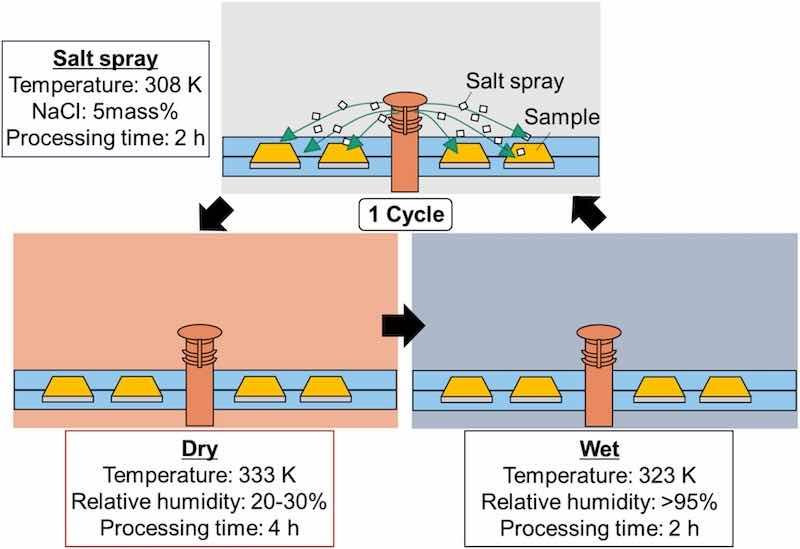
Fig. 2. Schematics and conditions for cyclic corrosion tests.
3. Results
3.1. Compounds formed on cavitation-treated surfaces
Each treated sample changed from metallic gray to a golden color, consistent with previous studies [[30], [31], [32], [33]]. This golden color is due to the formation of a film on the Mg alloy surface, and a cellular microstructure was observed by SEM (Fig. 3). This microstructure was observed on both the WJP- and MFC-treated surfaces. We have also previously reported that surface treatments with phosphoric acid in the cavitation bubbles slightly reduce hardness and residual stress but form films thicker than 1 μm, as shown in Table 2 [31]. Because the temperature inside the cavitation bubbles differs between WJP and MFC, we identified the chemical compounds in the films formed on the surfaces after the two treatments. The treated surfaces were analyzed by X-ray diffraction (XRD); however, no compounds were identified because the films formed by these treatments were thin. Because the interior of the cavitation bubble changes to a radical state, we conducted an FT-IR analysis to identify the compounds on the basis of the frequency of infrared light absorbed by the molecules.
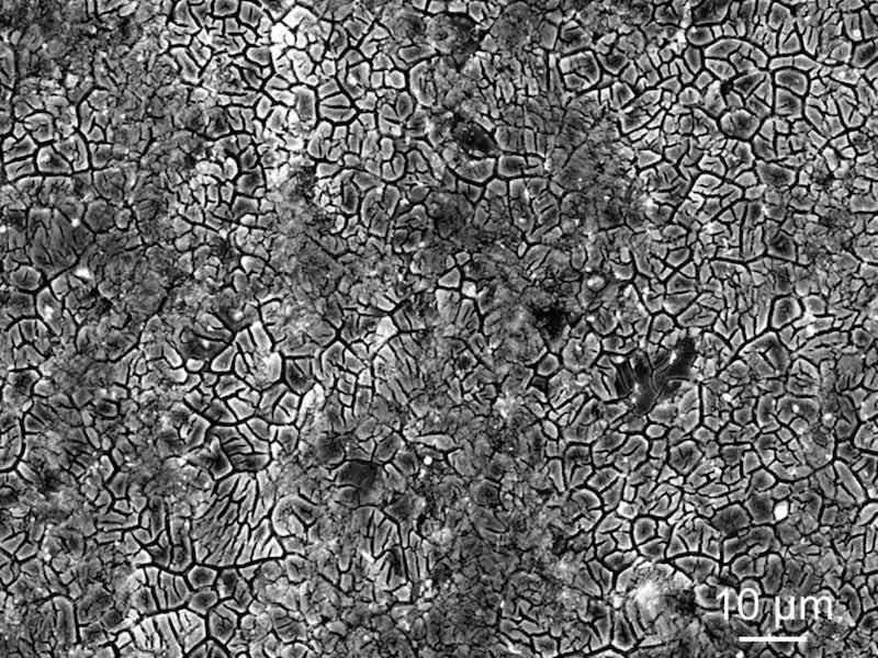
Fig. 3. SEM image of a sample after the MFC treatment.
Table 2. Surface characteristics after each treatment [31].
| Empty Cell | Residual stress (MPa) | Hardness (HV) | Film thickness (μm) |
| MFC | −115 ± 5.4 | 107.9 ± 6.6 | – |
| MFC (uses phosphoric acid) | −110 ± 7.1 | 79.0 ± 4.5 | 1.32 ± 0.17 |
| WJP | −109 ± 6 | 105.5 ± 5.8 | – |
| WJP (uses phosphoric acid) | −102 ± 9 | 90.6 ± 10 | 1.33 ± 0.06 |
Fig. 4 shows FT-IR spectra of the surfaces of untreated (UT) and treated samples. The broad band at 400–450 cm−1 can be assigned to Mgsingle bondO. The broad band at ∼570 cm−1 is the stretching vibration of the M–OH bond (M: metal). The peak at ∼1040 cm−1 can be assigned to M–PO43− [37,38]. These results indicate that the films formed on the Mg alloy surface by each cavitation treatment contained PO43−. The peak at ∼1640 cm−1 can be assigned to the bending vibration of HPO42− [39]. The peaks at 2500–3500 cm−1 are due to the stretching vibrations in the OH group [40]. These results suggest that the films contain metal oxides, hydroxides, and phosphoric acid-based compounds as components, consistent with the results of a previous study in which the surface after cavitation treatment was analyzed using GD-OES [30].
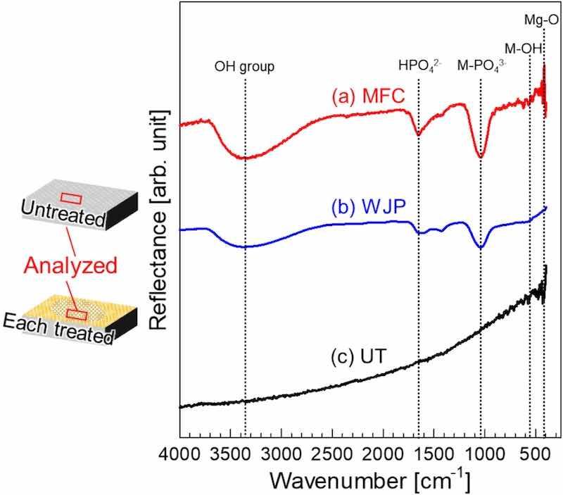
Fig. 4. FT-IR reflectance spectra of films on surfaces prepared by (a) MFC and (b) WJP, and (c) the film on a UT surface.
3.2. Evaluation of surfaces modified with various cavitation treatments in chloride solutions
To evaluate the corrosion resistance in chloride solutions, we carried out polarization measurements in a 5 mass% NaCl solution. Fig. 5 shows the anodic potentiodynamic polarization obtained from the UT and each cavitation-treated surface. The UT sample showed a corrosion potential of −1.54 V, and the potential increased monotonically but did not show a Tafel slope. By contrast, the corrosion potential of each treated sample was approximately −1.6 V, indicating passivation–depassivation behavior. Depassivation occurred at a current density of approximately 100 μA/cm2, and the potential of the MFC-treated sample was slightly higher than those of the WJP-treated sample and the UT sample.
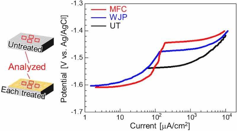
Fig. 5. Anodic polarization curves for a UT sample and each cavitation-treated sample in 5 mass% NaCl solution.
The cathodic polarization curves of the UT sample and each treated surface are shown in Fig. 6. The UT sample exhibited Tafel behavior, with a curve slope of −150 mV/decade. The samples after each treatment showed Tafel behavior with a gradient of −60 mV/decade from the corrosion potential to approximately −1.7 V. The behavior of the UT sample is attributed to the hydrogen evolution reaction [41]. However, for each treated sample, active hydrogen evolution reactions were observed at the surface at potentials of −1.7 V or greater. The corrosion rate was calculated from the Tafel slope of the cathode by the Tafel extrapolation method. The corrosion rate of the UT sample was 291 μA/cm2, whereas the initial corrosion rates of the treated materials were 32 and 36 μA/cm2, or approximately 1/10 that of the UT sample.
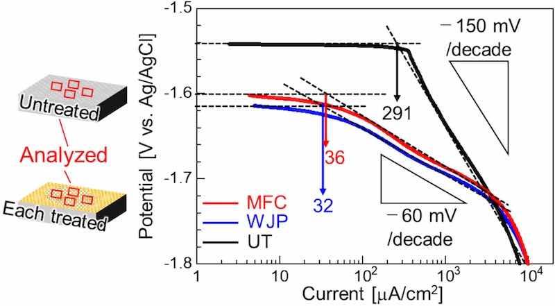
Fig. 6. Cathode polarization curves for the UT sample and each cavitation-treated sample in 5 mass% NaCl solution.
Fig. 7(a) shows Nyquist diagrams for samples obtained after 4 h of immersion in 5 mass% NaCl solution. All of the samples show a capacitive semicircle in the high frequency range, followed by an inductive loop in the low frequency range. Such behavior is typical for Mg undergoing corrosion and is expressed by the electrical equivalent circuit shown in Fig. 7(b) [42]. Because the center of the capacitive semicircle is located below the real axis, Z', we replaced one of the capacitive elements with a constant-phase element to reflect the inhomogeneity of the electrode surface. Curve-fitting analysis was performed; the result is superimposed on the experimental results in Fig. 7(a). The employed equivalent circuit adequately simulated the experimental system. The value for each element is listed in Table 3. Herein, the sum of R1 + R2 was selected as the resistance to the corrosion rate, i.e., the charge-transfer resistance, Rct [43].
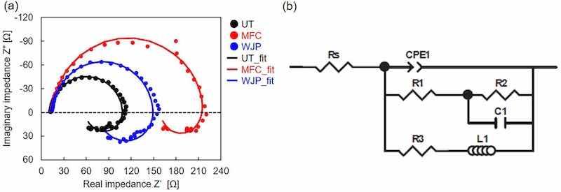
Fig. 7. Electrochemical impedance spectroscopy results: (a) Nyquist diagram for UT, WJP-treated, and MFC-treated samples immersed in 5 mass% NaCl solution for 4 h; (b) electrical equivalent circuit for corroding Mg.
Table 3. Results of fitting analysis of the electrochemical impedance spectroscopy data shown in Fig. 7(a).
| Empty Cell | Rs (Ω) | CPE1-T (−) | CPE-P (−) | R1 (Ω) | R2 (Ω) | C1 (F) | R3 (Ω) | L1 (Ωs) |
| UT | 12.2 | 3.89E-05 | 0.949 | 4.6 | 92 | 9.52E-06 | 93 | 78 |
| WJP | 13.1 | 2.00E-05 | 0.946 | 8.6 | 128 | 1.04E-05 | 119 | 155 |
| MFC | 13.1 | 3.28E-05 | 0.927 | 14.4 | 192 | 5.88E-06 | 513 | 235 |
The time variation of the reciprocal of Rct was analyzed (Fig. 8). Each treated sample showed a large Rct compared with that for the UT sample for up to 6 h, indicating that corrosion proceeded more slowly. However, this difference gradually diminished and Rct eventually matched that for the UT sample.
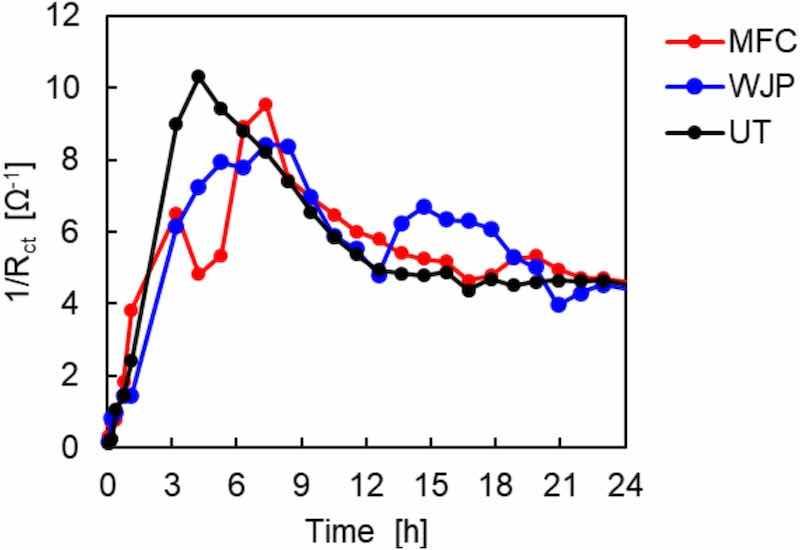
Fig. 8. Change in Rct with time for UT, MFC-treated, and WJP-treated samples immersed in 5 mass% NaCl solution.
The surface of each sample after 4 h of electrochemical impedance measurements is shown in Fig. 9. Black rust was observed over the entire UT sample; by contrast, the amount of black rust on each treated sample was small. It is likely that the amount of black rust gradually increases over time.
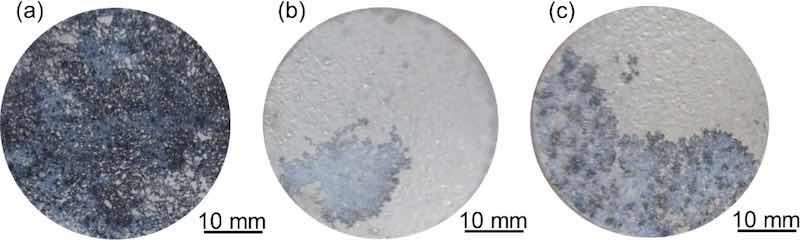
Fig. 9. Surface of each sample after 4 h of electrochemical impedance measurement.
The above results revealed that, although the films formed on the Mg alloys after each treatment exhibited a protective effect initially in a 5 mass% NaCl solution, the protective effect decreased over time.
3.3. Effect of chlorides formed at surfaces of films after various cavitation treatments in air
To evaluate the corrosion under conditions similar to those used in industrial processes, we carried out a combined cycle test on the coating formed after the cavitation treatment. Fig. 10 shows the UT surface and each treated surface after the combined cycle test. These surface photographs show the surface of each sample after the test and after the chlorides had been removed with a brush. For the UT sample, a large amount of chlorides remained on the surface. By contrast, small amounts of adhered chlorides were observed on the treated samples.
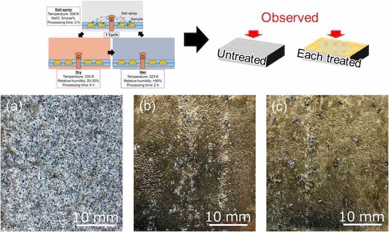
Fig. 10. Surface photographs of (a) UT, (b) WJP-treated, and (c) MFC-treated samples after combined cycle testing. The blue-white color is the chloride that adhered after the cycle test.
Fig. 11 shows a cross-sectional SEM image of samples after the combined cycle test. For the UT sample, cracks were observed from the outermost surface toward the depth direction. The oxygen map shows that oxidation due to chlorides was promoted on the UT surface, whereas oxidation was not promoted on the treated surfaces. No cracks were observed on either of the treated surfaces, and little oxidation due to surface chlorides occurred. In addition, dents were observed on the outermost surface after the WJP treatment. These dents are corrosion pits caused by cavitation bubbles. In the areas where these corrosion pits were formed, oxidation was progressing in line with the oxygen concentration map. We speculate that the coating in other parts of the film prevented oxidation by chlorides.
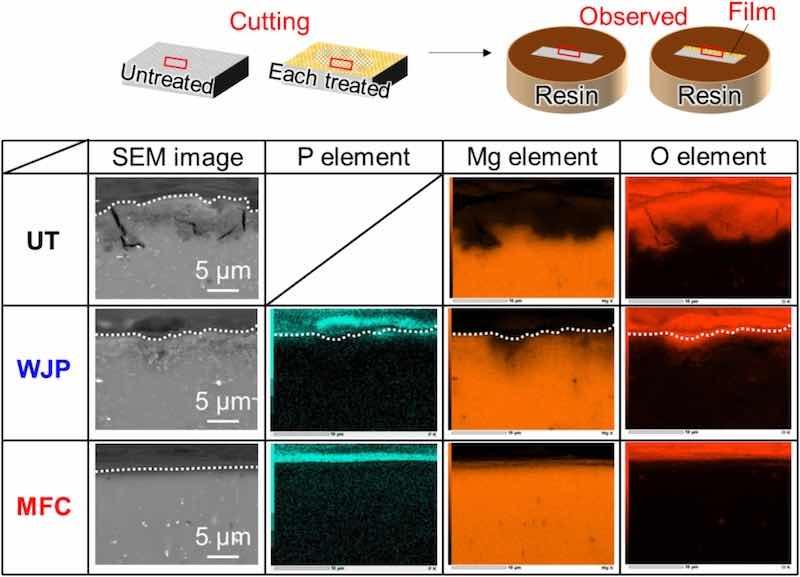
Fig. 11. SEM images and EDS elemental mappings of sample surfaces after various treatments. The dotted lines indicate the sample surface.
Because SEM observations are limited to localized areas, we used GD-OES analysis to evaluate the oxygen distribution in the depth direction from the surface (Fig. 12). In the UT sample, an increase in oxygen concentration after the combined cycle test was confirmed, similar to the results in Fig. 11. In the sample subjected MFC, the increase in oxygen concentration is small, indicating that oxidation was prevented. However, in the sample subjected to WJP, the oxygen concentration increased, indicating that oxidation had progressed. In a previous study, some areas with uneven film conditions were observed on the surface of a WJP-treated Mg alloy [30]. We speculate that localized non-uniformities exist in the state of the film formed on the surface after each treatment.
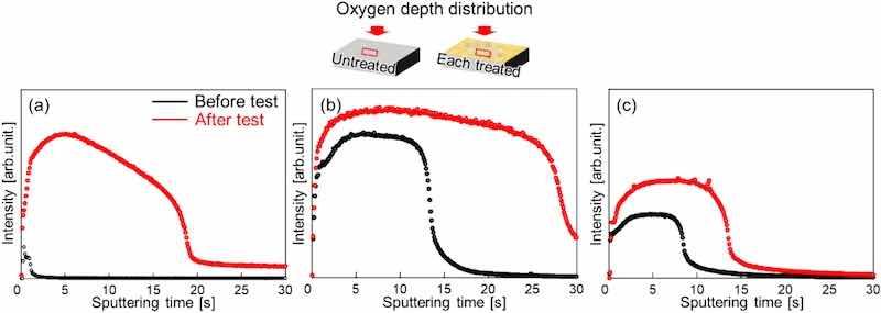
Fig. 12. Oxygen distribution from the surface to the depth of the (a) UT, (b) WJP-treated, and (c) MFC-treated samples.
4. Discussion
4.1. Process of film formation on the surface after cavitation treatment
On the basis of our film analysis results, we here discuss the compound formation process within the films. When an Mg alloy is immersed in a treatment solution that is neutral or acidic, Mg dissolution and H2 generation occur on the Mg alloy surface, as shown in (1), (2) [44]:
Mg → Mg2+ + 2e- (1)
2H+ + 2e- → H2 (2)
With the generation of Mg2+ in eq. (1), the anode current increases rapidly. As H2 is generated in eq. (2), the pH in the vicinity of the surface increases locally and Mg2+ ions react with OH− ions. We speculate that Mg(OH)2 is formed as shown in eq. (3):
Mg2+ + 2OH- → Mg (3)
In addition, in solutions containing Mg2+, Ca2+, Sr2+, and Ba2+ alkaline-earth metal cations and H3PO4, the increase in pH stagnates in three regions (pH 2–3, 6–7, and 10.5–11.5) and the three-step sequential reactions of phosphoric acid occur as shown in eqs. (4), (5), (6) [45]:
H3PO4 → H3 PO4- + H+ (4)
H2PO4- → H2 PO42- + H+ (5)
HPO42- → H2 PO43- + H+ (6)
At the microscopic anode site, an etching-like reaction occurs with free H3PO4 and a local potential difference is created by the anode and cathodic reactions. In addition, the increase in pH near the interface of the Mg alloy is thought to shift the equilibrium reaction toward the production of HPO42− and PO43−, which precipitates the film. The film formed by cavitation bubbles is thought to form insoluble compounds on the surface of the Mg alloy because of the dissolution reaction on the surface and the change in pH near the interface, resulting in a reaction between Mg2+ and PO43− ions (eq. (1)). The resultant film is formed as shown in eq. (7):
3 Mg2+ + 2PO43- → Mg3 PO3 (7)
From the above discussion, we speculate that the film formed on the surface after each cavitation treatment was a compound of Mg3(PO4)2 and Mg(OH)2. When a Mg alloy is immersed in H3PO4 alone [31] and the H3PO4 concentration is low, the dissolution reaction on the alloy surface is impeded and a thin film is likely to form. By contrast, when the H3PO4 concentration is high, the dissolution reaction is fast and heterogeneous products are therefore more likely to form. In the case of cavitation treatment, we speculate that the dissolution reaction was promoted by the impact force generated by the collapse of the cavitation bubbles, resulting in the formation of a coating with fewer nonuniform products larger than 1.2 μm, as reported in a previous study [31]. In addition, for these treatments, because water vapor is present inside the bubbles, endothermic chemical reactions such as the decomposition of water molecules are likely to occur; these reactions likely cause the surrounding temperature to decrease more than usual. However, reactive oxygen species such as hydroxyl radicals (•OH radicals) dissolve from the inside of the bubble to the liquid side, affecting the chemical reactions around the bubble and likely contributing to the formation of Mg(OH)2. The resultant Mg(OH)2 film prevents oxidation of the matrix of the substrate when it is used in alkaline or low-moisture environments [46]. However, when aggressive anions such as Cl−, SO42−, and CO32− ions are present, they can severely damage the passive Mg(OH)2 layer, leading to rapid exposure of the underlying matrix [47,48]. In addition, phosphate compounds such as Mg3(PO4)2 are expected to be used as luminescent materials [49]. We expect that the components of these films will be used in applications in a wide range of fields in the future.
4.2. Effect of electrochemical measurements on the films formed on the surface after each treatment
In the corrosion reactions of metallic materials, the anodic reaction in which the metal is ionized and the cathodic reaction in which H+ ions and O2 are reduced in various environments are coupled while electrical neutrality is maintained. The corrosion reaction of Mg in a neutral environment produces Mg(OH)2. In salt water, Mg(OH)2 dissolves because of the presence of Cl− ions. Mg reduces the reaction rate of the cathodic reaction accompanying hydrogen evolution under anodic polarization. In addition, hydrogen evolution has been reported to increase under anodic polarization [50,51]. In surface observations during polarization, corrosion has not been observed to occur at the points where H2 is generated under cathodic polarization; however, corrosion does occur at the points where H2 is generated under anodic polarization [52]. In addition, Mg corrosion involves a chunk effect [53,54] in which metal parts covered by the corrosion products fall off.
On cavitation-treated surfaces, the pseudo-passivation–depassivation phenomenon [55] was confirmed by anodic polarization measurements. This phenomenon has been confirmed in austenitic stainless steels [56] and in Mg/Al-alloy joints [57]. However, cathodic polarization measurements confirmed a Tafel slope of −60 mV/decade for the MFC-treated sample. This gradient is a rarely observed phenomenon. It is thought that reactions other than H2 generation are occurring, such as the reduction reaction of the phosphate film or a process involving cavitation bubbles.
Several elements of the surface treatment using cavitation in the chemical conversion coating process differ from those of the general chemical conversion coating process. Cavitation treatment requires placing the sample in water before the treatment, during which hydroxide-derived products are formed on the Mg-alloy surface. The Mg-alloy surface is treated using cavitation bubbles that contain H3PO4. During the surface treatment, when the cavitation bubbles collapse, the shock waves cause the hydroxide-derived products to peel off, thereby refining the surface grains after treatment. In fact, peeling of the plating on the surface of Ni-plated steel after cavitation treatment has been reported [25]. Alternatively, products derived from hydroxide before treatment might be included in the process of forming a phosphate film, rather than product peeling. However, with regard to refining the surface grains after treatment, when the surfaces of steels [34] and Al alloys [27,58] were treated with cavitation in previous studies, the hardness of the outermost surface increased and the microstructure was observed. In fact, previous research [31] has confirmed that the hardness of the surface of Mg alloys increases after treatment, suggesting that refinement is promoted at the outermost surface. In addition, because of the high-temperature state inside the cavitation bubbles [35], ions derived from H3PO4 and highly reactive unpaired electrons are formed, promoting chemical reactions to a greater extent. Therefore, we speculate that the cathode polarization curve showed a Tafel slope of −60 mV/decade because the cavitation treatment formed a surface state that differs from that formed by conventional chemical conversion treatments. In any case, the cause of the large potential difference will need to be investigated in future studies.
4.3. Homogeneity of the film formed on the surface after cavitation treatment
To investigate the nonuniformity of the film formed on the surface after treatment, the wettability of each sample surface with a 5 mass% NaCl solution was examined. Wettability is affected by the surface tension and interfacial tension of a solid. Because the chemical reaction between the film and the Cl− solution begins at the interface between the metal surface and the aqueous solution, we evaluated the angle at which the droplet was dropped (Fig. 13). Photographs showing the droplets adhering to the surface at each time interval are also presented. The smaller the angle of the droplet formed on the surface, the more hydrophilic the surface and the more the chemical reaction at the interface between the metal and the aqueous solution is promoted. In areas with good hydrophobic properties, the film protects the base metal surface from chlorides. In the UT sample, the angle of the droplet formed on the surface was constant at every examined location. However, differences in the angle of droplets formed on the surface of each treated material were observed, indicating that, after the treatment, some areas of the film were uneven. In a previous study, corrosion pits [31] were observed on the surface after each treatment; the presence of these pits, in addition to the condition of the film, is one of the factors affecting the corrosion behavior. This corrosion factor is also thought to be involved in the evaluations conducted in chloride solutions. Regarding each cavitation treatment, MFC, which involves higher temperatures in the cavitation bubbles before collapse during treatment, led to greater hydrophobicity toward chlorides than WJP, and the initial corrosion-resistant film was effective in forming the Mg-alloy surface. During the film formation process, the speed of the cavitation bubbles colliding with the target object is lower in the MFC process than in the WJP process. This lower speed allows the treatment of rotating surfaces such as gears [[23], [24], [25], [26]] and suppresses surface roughness after treatment. Therefore, MFC treatment is more effective than WJP in forming surfaces that are more resistant to chloride corrosion because the formation of irregularities is more difficult on the MFC-treated surfaces.
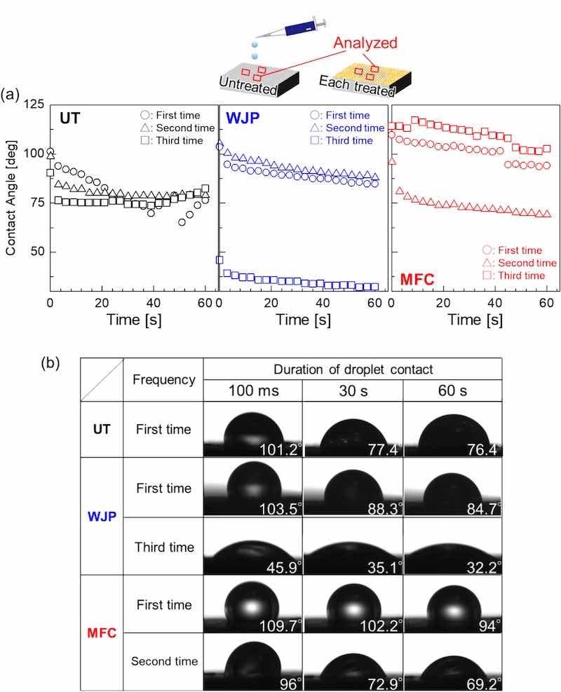
Fig. 13. (a) The contact angle of a droplet of 5 % NaCl solution dropped onto the surface of each sample and (b) the behavior of the droplet for different durations.
In the future, it will be necessary to develop a method for uniform surface processing and a method for preventing the formation of corrosion pits.
5. Conclusions
In this study, a film was formed on the surface of a Mg alloy via a process involving cavitation bubbles during a chemical conversion treatment. The chemical compounds of the resultant film were investigated, and its corrosion resistance to chlorides was evaluated. The following main conclusions are drawn:
(1) The compounds of the films formed by each cavitation treatment were speculated to be Mg3(PO4)2 and Mg(OH)2.
(2) In anodic potentiodynamic polarization, the corrosion potential of each treated sample was low (approximately −1.6 V) and the sample exhibited pseudo-passivation–depassivation behavior.
(3) In cathodic potentiodynamic polarization, the initial corrosion rates of the cavitation-treated samples were approximately 1/10 the value of the untreated sample.
(4) In the combined cycle test, the amount of oxidation by chlorides on the surface of the cavitation-treated samples was relatively less than that on the surface of the UT sample.
(5) Differences were observed in the droplet angles between the treated samples, and they showed hydrophobic behavior compared with the UT sample.
Written by Masataka Ijiria, Fumihiro Katob, Toshihiko Yoshimurab, Isao Nakatsugawac, Yasumasa Chinoc, and Shoichi Kikuchid
- Tokyo Metropolitan University, 6-6 Asahigaoka, Hino-shi, 192-0065 Tokyo, Japan
- Sanyo-Onoda City University, 1-1-1 Daigaku-Dori, Sanyo- Onoda, Yamaguchi 756-0884, Japan
- National Institute of Advanced Industrial Science and Technology, 4-205 Sakurazaka, Moriyama-ku, Nagoya, 463-8560 Japan
- Shizuoka University, 3-5-1 Johoku, Chuo-ku, Hamamatsu-shi, Shizuoka 432-8561, Japan
Masataka Ijiri: Writing – review & editing, Writing – original draft, Visualization, Supervision, Funding acquisition, Formal analysis, Data curation. Fumihiro Kato: Methodology, Data curation. Toshihiko Yoshimura: Supervision, Investigation, Formal analysis. Isao Nakatsugawa: Validation, Methodology, Data curation. Yasumasa Chino: Supervision, Formal analysis, Data curation. Shoichi Kikuchi: Supervision, Formal analysis, Data curation.
Acknowledgments: This work was supported by the Light Metal Educational Foundation and by Proterial Materials Science Foundation. The authors acknowledge the anonymous reviewers for their insightful and detailed comments that supported us in improving the scientific quality and presentation of this manuscript.
Data availability: No data was used for the research described in the article.
References
[1] T. Tarui, State of the arts multi material technologies in automotive industry, J. Japan Inst. Light Metals 72 (2022) 99–106, https://doi.org/10.2464/jilm.72.99.
[2] T. Nakata, S. Kamado, Development trend on magnesium alloy, J. Surf. Finish. Soc. Japan 71 (2020) 200–204, https://doi.org/10.4139/sfj.71.200.
[3] Q.C. Jiang, X.L. Li, H.Y. Wang, Fabrication of TiC particulate reinforced magnesium matrix composites, Scripta Mater. 48 (2003) 713–716, https://doi.org/ 10.1016/S1359-6462(02)00551-1.
[4] J. Gu, X. Zhang, Y. Qiu, M. Gu, Damping behaviors of magnesium matrix composites reinforced with Cu-coated and uncoated SiC particulates, Compos. Sci. Technol. 65 (2005) 1736–1742, https://doi.org/10.1016/j. compscitech.2005.02.014.
[5] S.Y. Chang, H. Tezuka, A. Kamio, Mechanical properties and structure of ignition- proof Mg–Ca–Zr alloys produced by squeeze casting, Mater. Trans. 38 (1997) 18–25, https://doi.org/10.2320/matertrans1989.38.526.
[6] T. Shinkawa, H. Kageyama, S. Kamado, Y. Kojima, Structures and mechanical properties of hybrid mg-Zn-ca alloy composites reinforced with δ-Al2O3 short fiber and 9Al2O3・2B2O3 whisker, J. Light Met. 46 (1996) 650–657, https://doi.org/ 10.2464/jilm.46.650. 9 M. Ijiri et al. [7] D. Wenbin, J. Haiyan, Z. Xiaoqin, L. Dehui, Y. Shoushan, Microstructure and mechanical properties of GTA surface modified composite layer on magnesium alloy AZ31 with SiCP, J. Alloys Compd. 429 (2007) 233–241, https://doi.org/ 10.1016/j.jallcom.2006.03.083.
[8] S. Sing, J. An, W. Yeong, F. Wiria, Laser and electron-beam powder-bed additive manufacturing of metallic implants: a review on processes, Mater. Des, J Orthop Res 34 (2016) 365–551, https://doi.org/10.1002/jor.23075.
[9] C.-M. Chan, T.-M. Ko, H. Hiraoka, Polymer surface modification by plasmas and photons, Surf. Sci. Rep. 24 (1-2) (1996) 1–54, https://doi.org/10.1016/0167-5729 (96)80003-3.
[10] H. Altun, S. Sen, The effect of DC magnetron sputtering AlN coatings on the corrosion behaviour of magnesium alloys, Surf. Coat. Technol. 197 (2005) 193–200, https://doi.org/10.1016/j.surfcoat.2004.06.001.
[11] G. Song, D. Haddad, The topography of magnetron sputter-deposited mg–Ti alloy thin films, J. Mater. Chem. 125 (2011) 548–552, https://doi.org/10.1016/j. matchemphys.2010.10.018.
[12] S. Zhang, T. Liu, C. Li, S. Yao, C. Li, G. Yang, M. Liu, Atmospheric plasma-sprayed La0.8Sr0.2Ga0.8Mg0.2O3 electrolyte membranes for intermediate-temperature solid oxide fuel cells, J. Mater. Chem. A 3 (2015) 7535–7553, https://doi.org/ 10.1039/C5TA01203A.
[13] R. Hui, Z. Wang, O. Kesler, L. Rose, J. Jankovic, S. Yick, R. Maric, D. Ghosh, Thermal plasma spraying for SOFCs: applications, potential advantages, and challenges, J. Power Sources 170 (2007) 308–323, https://doi.org/10.1016/j. jpowsour.2007.03.075.
[14] K. Nakazawa, T. Ohashi, S. Saiki, S. Kikuchi, Local oxynitriding of AZ31 magnesium alloy by atmospheric-pressure plasma treatment at room temperature, J. Magnes. Alloy. 8 (2020) 42–65, https://doi.org/10.1016/j.jma.2021.11.008.
[15] S. Kikuchi, S. Iwamae, H. Akebono, J. Komotori, Y. Misaka, Improvement of the electrochemical characteristics of medium carbon steel using atmospheric- controlled induction-heating fine particle peening, Surf. Coat. Technol. 354 (2018) 76–82, https://doi.org/10.1016/j.surfcoat.2018.09.021.
[16] S. Kikuchi, S. Iwamae, H. Akebono, J. Komotori, K. Kadota, Effect of atmospheric- controlled induction-heating fine particle peening on electrochemical characteristics of austenitic stainless steel, Surf. Coat. Technol. 334 (2018) 189–195, https://doi.org/10.1016/j.surfcoat.2017.08.001.
[17] H. Soyama, Comparison between the improvements made to the fatigue strength of stainless steel by cavitation peening, water jet peening, shot peening and laser peening, J. Mater. Process. Technol. 269 (2019) 65–78, https://doi.org/10.1016/j. jmatprotec.2019.01.030.
[18] H. Soyama, Cavitation peening: a review, Metals 10 (2) (2020), https://doi.org/ 10.3390/met10020270.
[19] H. Soyama, Introduction of compressive residual stress using a cavitating jet in air, J. Eng. Mater. Technol. 126 (1) (2004) 123–128, https://doi.org/10.1115/ 1.1631434.
[20] T. Yoshimura, K. Tanaka, N. Yoshinaga, Development of mechanical- electrochemical cavitation technology, J. Jet. Flow Eng 32 (2016) 10–17.
[21] T. Yoshimura, K. Tanaka, N. Yoshinaga, Nano-level material processing by multifunction cavitation, Nanosci. Nanotechnol.–Asia 8 (2018) 41–54, https://doi. org/10.2174/2210681206666160922164202.
[22] T. Yoshimura, K. Tanaka, N. Yoshinaga, Material processing by mechanical- electrochemical cavitation, in: BHR Group 2016 Water Jetting, 2016, pp. 223–235.
[23] S. Kikuchi, K. Minamizawa, T. Ogi, K. Ono, T. Yoshimura, M. Ijiri, Effect of multifunction cavitation on rotating bending fatigue properties of steel rods and its fatigue limit estimation, Int. J. Fatigue 176 (2023) 107852, https://doi.org/ 10.1016/j.ijfatigue.2023.107852.
[24] S. Kikuchi, K. Ono, T. Yoshimura, M. Ijiri, Estimating the fatigue limits for quenched and tempered steel rods treated with multifunction cavitation considering residual stress, hardness, and surface pits, Fatigue Fract. Eng. Mater. Struct. 47 (2024) 4000–4011, https://doi.org/10.1111/ffe.14415.
[25] M. Ijiri, T. Yoshimura, Effect of multifunction cavitation treatment on helical gear surface, J. Mater. Eng. Perform. (2025), https://doi.org/10.1007/s11665-025- 10723-7.
[26] S. Kikuchi, K. Minamizawa, T. Yoshimura, M. Ijiri, Effect of multifunction cavitation processing on fatigue properties of carburized steel rods with smooth surface, Int. J. Fatigue 198 (2025), https://doi.org/10.1016/j. ijfatigue.2025.109034, 109034 In press.
[27] T. Yoshimura, M. Ijiri, D. Shimonishi, K. Tanaka, Micro-forging and peening aging produced by ultra-high-temperature and pressure cavitation, Int. J. Advancements Technol. 10 (2019), https://doi.org/10.4172/0976-4860.1000227.
[28] S. Kikuchi, S. Matsuoka, T. Yoshimura, M. Ijiri, Effect of natural aging by multifunction cavitation on plane bending fatigue behaviour of heat-treatable Al- Si7Mg aluminum alloys and its fatigue strength estimation, Int. J. Fatigue 185 (2024) 108352, https://doi.org/10.1016/j.ijfatigue.2024.108352.
[29] M. Ijiri, T. Yoshimura, Sustainability of compressive residual stress on the processing time of water jet peening using ultrasonic power, Heliyon 4 (2018) e00747, https://doi.org/10.1016/j.heliyon.2018.e00747.
[30] M. Ijiri, D. Shimonishi, S. Tani, N. Okada, M. Yamamoto, D. Nakagawa, K. Tanaka, T. Yoshimura, Improvement of corrosion resistance of magnesium alloy by high- temperature high-pressure cavitation treatment, Int. J. Lightweight Mater. Manuf. 2 (2019) 255–260, https://doi.org/10.1016/j.ijlmm.2019.02.001.
[31] M. Ijiri, K. Yamaguchi, S. Kikuchi, F. Kato, Y. Kunieda, H. Sakurai, T. Ogi, T. Yoshimura, Formation of a phosphoric acid compound film on an AZ31 magnesium alloy surface using cavitation bubbles, Surf. Interfaces 25 (2021) 101194, https://doi.org/10.1016/j.surfin.2021.101194.
[32] M. Ijiri, F. Kato, D. Maeda, D. Shimonishi, T. Yoshimura, Effect of compressive residual stress on film formed by mechanochemical multifunction cavitation Surface & Coatings Technology 511 (2025) 132308 processing, Mater. Sci. Forum 1016 (2021) 574–579, https://doi.org/10.4028/ www.scientific.net/MSF.1016.574.
[33] S. Matsuoka, F. Kato, T. Yoshihiko, M. Ijiri, S. Kikuchi, Effect of multifunction cavitation using phosphoric acid on fatigue and surface properties of AZ31 magnesium alloy, J. Mag. Alloy 11 (6) (2023) 1996–2005, https://doi.org/ 10.1016/j.jma.2023.04.005.
[34] M. Ijiri, T. Ogi, T. Yoshimura, K. Minamizawa, S. Kikuchi, Effect of multifunction cavitation on microstructure and plane bending fatigue properties of low-alloy steel, Res Mater. 10 (2024) 100578, https://doi.org/10.1016/j. rinma.2024.100578.
[35] T. Yoshimura, N. Nishijima, D. Hashimoto, M. Ijiri, Sonoluminescence from ultra- high temperature and pressure cavitation produced by a narrow water jet, Heliyon 7 (2021) e07767, https://doi.org/10.1016/j.heliyon.2021.e07767.
[36] M. Ijiri, D. Shimonishi, S. Tani, N. Okada, M. Yamamoto, D. Nakagawa, K. Tanaka, T. Yoshimura, Multifunction cavitation technology to improve the surface function of Al - cu alloy, Int. J. Lightweight Mater. Manuf. 2 (2019) 50–56, https://doi.org/ 10.1016/j.ijlmm.2018.12.001.
[37] K. Lertjiamratn, P. Praserthdam, M. Arai, Joongjai Panpranot, Modification of acid properties and catalytic properties of AlPO4 by hydrothermal pretreatment for methanol dehydration to dimethyl ether, Appl. Catal. A Gen. 378 (1) (2010) 119–123, https://doi.org/10.1016/j.apcata.2010.02.013.
[38] Z. He, W. Honeycutt, T. Zhang, P. Bertsch, Preparation and FT–IR characterization of metal phytate compounds, J. Environ. Qual. 35 (2006) 1319–1328, https://doi. org/10.2134/jeq2006.0008.
[39] X. Cui, Q. Li, Y. Li, F. Wang, G. Jin, M. Ding, Microstructure and corrosion resistance of phytic acid conversion coatings for magnesium alloy, App. Surf. Sci. 255 (5) (2008) 2098–2103, https://doi.org/10.1016/j.apsusc.2008.06.199.
[40] S. Kaewgun, C.A. Nolph, B.I. Lee, L. Wang, Influence of hydroxyl contents on photocatalytic activities of polymorphic titania nanoparticles, Mater. Chem. Phys. 114 (1) (2009) 439–445, https://doi.org/10.1016/j.matchemphys.2008.09.072.
[41] S. Fajardo, J. Bosch, G.S. Frankel, Anomalous hydrogen evolution on AZ31, AZ61 and AZ91 magnesium alloys in unbuffered sodium chloride solution, Corros. Sci. 146 (2019) 163–171, https://doi.org/10.1016/j.corsci.2018.10.039.
[42] I. Nakatsugawa, N. Saito, K. Suzuki, Y. Chino, Y. Fukuda, T. Ito, M. Noda, Y. Gonda, Influence of Al concentration and Zn addition on the corrosion resistance of rolled Mg–Al–(Zn)–Ca magnesium alloys, Mater. Trans. 61 (2020) 1798–1804, https:// doi.org/10.2320/matertrans.L-M2020839.
[43] M. Curioni, F. Scenini, T. Monetta, F. Bellucci, Correlation between electrochemical impedance measurements and corrosion rate of magnesium investigated by real-time hydrogen measurement and optical imaging, Electrochim. Acta 166 (2015) 372–384, https://doi.org/10.1016/j. electacta.2015.03.050.
[44] N. Kamiyama, T. Ishizaki, Preparation of corrosion resistant film on magnesium alloy by steam coating, J. Japan Inst. Light Metals. 64 (12) (2014) 638–642, https://doi.org/10.2464/jilm.64.638.
[45] A. Nakamura, S. Oue, H. Koga, H. Nakano, Formation behavior of phosphoric acid- based chemical conversion coating containing alkaline earth metals on magnesium alloy, J. Japan Inst. Met. Mater. 80 (11) (2016) 684–690, https://doi.org/10.2320/ matertrans.M2016463.
[46] K. Chong, T. Shih, Conversion-coating treatment for magnesium alloys by a permanganate–phosphate solution, Mater. Chem. Phys. 80 (2003) 191–200, https://doi.org/10.1016/S0254-0584(02)00481-9.
[47] G.L. Makar, J. Kruger, Corrosion of magnesium, Int. Mater. Rev. 38 (3) (1993) 138–153, https://doi.org/10.1179/imr.1993.38.3.138.
[48] K.R. Baldwin, D.J. Bray, G.D. Howard, R.W. Gardiner, Corrosion behaviour of some vapour deposited magnesium alloys, Mater. Sci. Technol. 12 (1996) 937–943, https://doi.org/10.1179/mst.1996.12.11.929.
[49] I.M. Nagpure, S.S. Pitale, E. Coetsee, O.M. Ntwaeaborwa, J.J. Terblans, H.C. Swart, Low voltage electron induced cathodoluminescence degradation and surface characterization of Sr3(PO4)2:Tb phosphor, Appl. Surf. Sci. 257 (2011) 10147–10155, https://doi.org/10.1016/j.apsusc.2011.07.008.
[50] G. Song, A. Atrens, D. St John, X. Wu, J. Nairn, The anodic dissolution of magnesium in chloride and sulphate solutions, Corros. Sci. 39 (1997) 1981–2004, https://doi.org/10.1016/S0010-938X(97)00090-5.
[51] G. Song, A. Atrens, D. St John, J. Nairn, Y. Li, The electrochemical corrosion of pure magnesium in 1 N NaCl, Corros. Sci. 39 (1997) 855–875, https://doi.org/ 10.1016/S0010-938X(96)00172-2.
[52] G.L. Song, Corrosion of Magnesium Alloys, Woodhead, 2011, pp. 3–65.
[53] B.A. Shaw, in: S.D. Cramer, B.S. Covino Jr. (Eds.), Corrosion: fundamentals, testing, and protection, ASM Int., 2003, pp. 692–696.
[54] W.J. James, M.E. Straumanis, B.K. Bhatia, J.W. Johnson, The difference effect on magnesium dissolving in acids, J. Electrochem. Soc. 110 (1963) 1117–1120, https://doi.org/10.1149/1.2425601.
[55] I. Nakatsugawa, H. Takayasu, K. Araki, T. Tsukeda, Electrochemical corrosion studies of thixomolded AZ91D alloy in sodium chloride solution, Mater. Sci. Forum 419-422 (2003) 845–850, https://doi.org/10.4028/www.scientific.net/MSF.419- 422.845.
[56] L. Reclaru, F. lonescu, F. Diologent, Evaluation of the corrosion resistance of watch links from 316L and 904L austenitic stainless steels obtained by the metal injection 10 M. Ijiri et al. molding (MIM) technique intended to be in contact with human skin, Coatings 14 (4) (2024) 412, https://doi.org/10.3390/coatings14040412.
[57] I. Nakatsugawa, Y. Chino, Effect of NaCl concentration on the galvanic corrosion behavior of a magnesium AZX611/aluminum A6N01 alloy joint, J. Electrochem. Soc. 167 (2020) 061501, https://doi.org/10.1149/1945-7111/ab7c70. Surface & Coatings Technology 511 (2025) 132308 [58] M. Ijiri, T. Ogi, T. Yoshimura, Effect of multifunction cavitation treatment on the surface of thin plates of Al alloys, Res. Mater. 16 (2022) 100329, https://doi.org/ 10.1016/j.rinma.2022.100329.