This article introduces Pulse Anodizing, a versatile electrochemical process that offers enhanced control over the formation of oxide layers on aluminum.
 Anne Deacon JuhlPulse anodizing involves alternating between different voltage or current levels during the anodizing process, as opposed to maintaining a constant value throughout.
Introduction to Anodizing
Anodizing is a widely used electrochemical surface treatment that enhances the corrosion resistance, wear resistance, and aesthetic properties of aluminum by artificially thickening its natural oxide layer. This is achieved by applying an anodic current or voltage to an aluminum part immersed in an acidic electrolyte, typically sulfuric acid. The anodizing process is an electrochemical conversion of the aluminum surface into aluminum oxide (Al2O3).
The first process developed and patented was in 1923 and called the Bengough-Stuart process [ref 1], anodizing has since evolved into a sophisticated process with multiple variations tailored to specific applications. While sulfuric acid remains the most commonly used electrolyte, other acids, such as chromic acid and phosphoric acid, have been adopted for specialized applications, including aerospace components and adhesive bonding.
This article will focus specifically on an in-depth exploration of pulse anodizing in sulfuric acid solutions.
Sulfuric Acid Anodizing
Sulfuric acid anodizing process is the most extensively studied and widely applied anodizing process due to its versatility and well-established operating parameters, often called mature. The process is influenced by key factors such as electrolyte temperature, acid concentration, and current density, all of which affect the thickness, porosity, and mechanical properties of the oxide layer, see figure 1.
![Figure 1, variations in process parameters and their influence on the aluminum oxide layer formed [REF2]](/images/images/annedeaconjuhl/theorypa/figure_1.jpg)
Figure 1, variations in process parameters and their influence on the aluminum oxide layer formed [REF2]
The final thickness of the oxide layer depends on the balance between formation and dissolution rates, which eventually reach a steady-state equilibrium. Depending on the application, the anodized aluminum surface can be left in as its artificial formed porous state for enhanced adhesion properties and wear properties or sealed to improve corrosion resistance and capture colors.
Anodizing has long been regarded as a mature. However, recent advancements are transforming it into a highly controlled engineering discipline. Groundbreaking work, such as that of Judy Runge [REF 3], has disrupted traditional understanding by establishing a critical connection between substrate metallurgy and oxide growth mechanisms. This shift enables engineers to optimize oxide quality even on the most complex alloys.
Linking substrate microstructure to oxide formation, anodizing strategies can now be precisely engineered to achieve greater coating uniformity, improved properties and high consistency. This is where pulse anodizing becomes an even more important player in the game.
Automation further advances anodizing, with real-time monitoring of the process parameters ensuring consistency. By integrating metallurgical insights, pulse anodizing, and automation, anodizing is no longer just a surface treatment - it is a precision-engineered, high-performance process.
Let´s start by looking at the formation of the porous oxide layer to figure out what we are talking about.
Formation of the Porous Oxide Layer
The formation of a porous anodic oxide layer on aluminum in sulfuric acid occurs through a combination of oxide formation and chemical dissolution in an acidic electrolyte.
Considering the formation of the porous oxide layer, reactions (1) and (2) provide only a partial explanation of the aluminum oxide formation process.
Reaction (1) represents the formation of aluminum oxide:
2Al + 3H2O → Al2O3 + 6H+ + 6e-
Reaction (2) describes the chemical dissolution of the oxide layer in an acidic electrolyte, such as sulfuric acid:
Al2O3 + 6H+ → 2Al3+ + 3H2O
If chemical dissolution were the only dissolution mechanism at play, it would be difficult to explain certain observations. Specifically, how can the dissolution rate increase proportionally to maintain a steady-state oxide thickness when the film growth rate nearly doubles as the current density increases from 1 A/dm² to 2 A/dm² under identical anodizing conditions?
Traditionally explained, the porous oxide layer forms as aluminum oxide grows at the metal interface while simultaneously dissolving at the electrolyte interface. However, Judy Runge's recent work has introduced new insights into the mechanisms governing pore formation. She suggests that the initial formation of porosity is not solely dictated by chemical dissolution but also by localized stress effects and mechanical instability in the growing oxide layer, see figure 2.
![Figure 2, schematic drawing of aluminum oxide nucleation and growth [REF 2]Figure 2, schematic drawing of aluminum oxide nucleation and growth [REF 2]](/images/images/annedeaconjuhl/theorypa/Figure_2.jpg)
Figure 2, schematic drawing of aluminum oxide nucleation and growth [REF 2]
Standard Sulfuric Acid Anodizing
Type II anodizing, also known as conventional or standard sulfuric acid anodizing, is the most common and versatile anodizing method. It creates a moderately thick oxide layer, typically ranging from 5 to 25 µm (0,2 mils – 1 mils), which enhances corrosion resistance, improves surface durability, and provides an excellent base for secondary treatments such as coloring and sealing.
The book Surface Treatment and Finishing of Aluminum and Its Alloys by Wernick, Pinner, and Sheasby [REF 1] compiles work done up until 1987. This resource covers sulfuric acid anodizing and discusses various other aluminum surface treatments.
According to this reference, the British Anodizing Association provides specific recommendations for architectural anodizing:
- Temperature: 18–20°C (±1°C)
- Electrolyte concentration: 160–185 g/l (±10 g/l)
- Current density: 1.4–2.0 A/dm², with adequate electrolyte agitation
- Voltage range: Typically 17–21 V
These conditions ensure consistent, high-quality anodized finish, making them widely adopted in industries like architectural applications, design and medical.
High-Performance Oxide Coatings
Hard anodizing, also known as Type III anodizing, is a specialized process designed to produce a thicker, denser, and harder oxide layer, typically exceeding 25 µm in thickness. This process often uses sulfuric acid or mixtures and is widely used in applications where high wear resistance, low friction, and superior durability are required, such as in automotive, aerospace, and industrial components.
The resulting oxide layer is highly wear-resistant, with a microhardness comparable to that of hardened steel. Additionally, it can be impregnated with lubricants or pigments to enhance its functionality for specific applications.
This is achieved most commonly by maintaining a low electrolyte temperature and a low electrolyte concentration to slow the chemical dissolution of the oxide layer. As a result, hard anodizing is typically performed in 5–15% (vol) sulfuric acid solutions at temperatures ranging from -5 to 5°C (23 to 41°F).
To produce very thick coatings, the process requires high current densities, which, in turn, necessitate the use of high voltages. These conditions generate localized temperature increases, making electrolyte agitation crucial to prevent overheating. Without proper agitation, the combination of high current densities and elevated local temperatures significantly increases the risk of burning.
Introduction to Pulse Anodizing
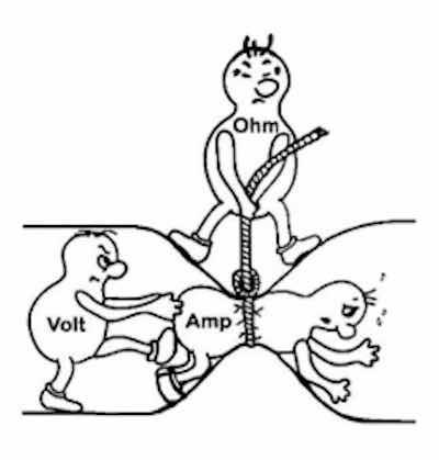
 Figure 3, Ohm´s law showing how the three parameters in the anodizing process are related to each otherOhm´s law
A key principle in anodizing is that current, not voltage, determines the formation of the aluminum oxide layer. The thickness of the oxide layer is dictated by the total amperage applied over time, making current control a critical factor in achieving the desired coating properties and consistency.
During anodizing, electrical power is applied to create a circuit where current flows between the aluminum workpiece (anode) and the cathode, both submerged in an electrolyte solution. This process follows Ohm’s Law, which states that the current in a system is dependent on both the applied voltage and the resistance present in the total electrical circuit.
Ohm´s law is V(Volt) = I (Amp) x R (Ohm)
Voltage can be thought of as the driving force attempting to push current through the electrolyte solution, while resistance dictates how easily the current can flow, see figure 3. As the oxide layer develops, resistance increases, making it progressively more difficult for the same voltage to sustain the original current level applied. This natural resistance buildup impacts the anodizing process and requires adjustments to maintain optimal conditions.
According to Runge the voltage can be divided into two parts one which represents the surface polarization of the anode, and the second is represented by the concentration polarization effects, also measured in volts, which represent the effects created by the rest of the anodizing circuit.
Following this approach gives the anodizing process an important new dimension – there are three types of current density which forms the oxide layer:
- The applied current density set by the process - ia
- The exchange current density which reflects the local changes in the interface – io
- The limiting current density is the rate of hydrogen ions through oxide, electrolyte and finally to the cathodes and is affected by the process parameters- iL
So basically, the exchange current density can be compared with what was called the barrier layer in the old days. It is here that the current is shifted from being carried by electrons to being carried by ions. Quated by Runge at the AAC conference in 2018 [REF 4] “So long as the exchange current density, io, across the aluminum anode is uniform, an oxide structure with uniform dimensions will be produced.”
The recovery effect
It was probably not until the ideas by Murphy [REF1] back in 1961 that the recovery effect was mentioned the following way:
If an anodizing voltage E1 is quickly reduced to a lower value E2, the current falls to a very low value and may take a considerable period amounting to minutes to attain the steady state condition characteristic of the second voltage: but if the voltage reduction is carried out slowly the recovery is very much quicker.
This recovery effect, as claimed by Murphy, is affected by:
- The values of E1and E2as well as the differences E1-E2.
- The rate of change of E from E1to E2.
- The concentration of the electrolyte in which the anodic coating at E1was formed.
- The temperature of the electrolyte in which the recovery process occurred.
- The treatment of the anodic coating between the time E1was switched off and E2 The drying of the film between formation and recovery approximately doubled the recovery time.
Murphy postulated that the readjustment of the barrier layer to the new voltage E2 is field assisted. Therefore, the recovery effect should be dependent on field-assisted migration of protons out of the film and/or neutralization of protons by field assisted migration of anions into the film.
Several years later Takahashi, Nagayama, Akahori and Kitahara [REF 5] presented their explanation of the recovery phenomenon. According to these authors the main features of the recovery effect can be explained by figure 4.
When the high voltage E1 is applied, the current will reach a steady level i1, stage 1 in figure 4. In this period the barrier layer will reach a thickness d1 corresponding to the forming voltage E1. The structure of the cells will also be controlled by E1.
![Figure 4, The recovery effect [REF 5]](/images/images/annedeaconjuhl/theorypa/Figure_4.jpg)
Figure 4, The recovery effect [REF 5]
When the voltage is suddenly lowered to E2 the current density will decrease drastically to a very small value as seen in stage 2. This small current density with values in the range of µA, corresponds to the very high resistance in the barrier layer d1. The electrical field across the barrier layer in this period is very low. Hence the formation of oxide is almost zero and the field assisted dissolution also very slow. The main reaction in this period will be the chemical dissolution of oxide, reaction (2). This period is called the recovery period.
After a certain time, dependent on many factors such as alloying elements, concentration of the electrolyte, temperature and the value of DE, the thickness of the barrier layer has become thinner hereby increasing the electrical field across the barrier layer. Now the field-assisted dissolution and formation will take place increasing the total dissolution rate as seen by the steep increase in current density during stage 3, due to a less resistance in the reduced thickness of the oxide layer.
After a while the current density will reach a steady level corresponding to the value of E2, see stage 4. Now the barrier layer thickness has reached the value d2 (less than d1) that corresponds to the voltage E2. The oxide will also adopt another dimension with smaller cells corresponding to E2 and appearing beneath the oxide layer formed at E1.
The dependency of DE, as Murphy postulated, is confirmed by Takahashi et al. [REF 5] “The larger the value DE the longer is the recovery time t2 beyond which the current increases steeply”.
The structural change according to the different stages are as explained. In stage 1 the forming voltage has a value of E1 and anodizing at this value will give a certain oxide structure and will give a uniform oxide layer with an array of hexagonal cells of same size.
In stage 2 the forming voltage is abruptly decreased to a lower value E2. This will make the electrical field across the barrier layer, which still has the thickness d1, very small. This results in a zero formation rate of oxide. The dissolution will slowly increase during this period and the barrier layer will gradually diminish to an appropriate value.
In stage 3, the thickness of the barrier layer has reached a level where the field strength has increased enough and suddenly the current increases steeply. The new cells formed are smaller and with a barrier layer thickness d2. In stage 4 the anodizing process continues at the current density i2 creating a uniform oxide layer with characteristic array of hexagonal cells until the voltage is increased again.
Pulse Anodizing
![Figure 5, Schematic current â time curve for pulse anodizing showing the choice of parameters [REF 6]](/images/images/annedeaconjuhl/theorypa/Figure_5.jpg) Figure 5, Schematic current – time curve for pulse anodizing showing the choice of parameters [REF 6]Pulse anodizing is a process where the voltage or current is alternated between two levels, rather than staying at a constant value throughout the process. This method allows for greater control over the oxide layer that forms on the aluminum material.
Figure 5, Schematic current – time curve for pulse anodizing showing the choice of parameters [REF 6]Pulse anodizing is a process where the voltage or current is alternated between two levels, rather than staying at a constant value throughout the process. This method allows for greater control over the oxide layer that forms on the aluminum material.
Pulsing can be achieved using direct current (DC) square wave pulses, which can vary in frequency, duty cycle, and amplitude or AC anodizing, where alternating current (AC) is used instead of direct current (DC). This method has a couple of practical limitations, the main is probably during the cathodic half-cycle of the AC waveform, no oxide formation occurs. This reduces the overall efficiency of the anodizing process since approximately half of the current does not contribute to oxide growth. These limitations make AC anodizing less desirable for many applications, despite the fact that it can be used for specific purposes such as creating specific surface finishes on difficult alloys e.g. 2024 or modifying the oxide's properties to make it easier to color hard anodized coatings.
The concept of pulse anodizing using low-frequency square wave pulses was first introduced by Yokoyama et al. In low-frequency pulse anodizing, the t₁ is often longer than the t₂, with pulse durations ranging from 10 to 180 or more seconds. The voltage varies depending on the aluminum alloy and the electrolyte temperature, while current densities range from 2 to 20 A/dm². A commonly used anodized parameters ratio is i₂ = i₁ × 0.75, where i₁ is determined based on the specific aluminum substrate being anodized [REF 6].
Instead of applying a constant direct current throughout the anodizing process, pulse anodizing alternates between two current values, allowing for greater control over process conditions. A schematic representation of square wave pulse cycles is shown in Figure 5. Various researchers have proposed different pulse designs.
One of the reasons for using pulse anodizing instead of conventional anodizing is a reduction in total treatment time and the possibility of avoiding burning and powdering problems. The next section will discuss these two destructive effects.
Burning and Powdering
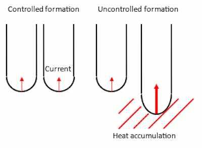
 Figure 6, simplified drawing of the burning phenomenon.The interface where the exchange current density operates is often described without considering the microstructural changes in the substrate. Yokoyama et al. [REF 7, 8] claimed that the interface is not smooth on a microscopic scale, as shown in the schematically drawing in figure 6. They explained it with metallic aluminum extending as many small projections as possible into the barrier layer. These small projections are not always metallic aluminum but consists also of variations of small, localized differences depending on the aluminum alloy anodized, forming small shifts in surface chemical potentials.
During anodizing, the anodic current tends to concentrate in areas where the current runs differently that on the rest of the substrate giving an uneven growth and destruction of the oxide layer described as burning by the authors [REF 7, 8]. When the current density is high, and the temperature of the electrolyte is low the balance between formation and dissolution is difficult to maintain – this is very often the case in hard anodizing. These variations in surface chemical potentials will transport the current density easier than the aluminum oxide and give rise to a short circuit through the interface in these pores depending on the alloying elements. When the current density concentrates in these pores the temperature will rise at the bottom of the pores, see figure 6 and will be a drastic increase in current, when R 0. The temperature will rise because of the effect P = R x I2. Whereas the in pores without these small surface imperfections will have a higher resistance and by this only a low current flow.
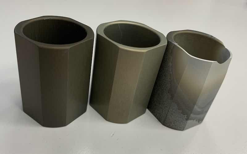
In pores with high formation rate of oxide the temperature will increase drastically. A thick oxide layer will be formed here, and the temperature will increase further due to Joule’s heat, which will lead to an increase in the rate of chemical dissolution. Hence the oxide layer will be non-uniform and in some places the electrolyte even attacks the underlying aluminum, see figure 7.

Figure 7, image of 3 different steps of the burning on a hard anodized load
To avoid burning the current density should be low. Hereby the chemical dissolution reaction (2), will be able to dissolve irregularities in the interface and anodizing will create a uniform oxide layer. However, lower current density means lower formation rate of the oxide, reaction (1), and hereby a longer treatment time to obtain a certain thickness of the oxide layer.
Powdering appears as a consequence of a prolonged treatment time. The acidic electrolyte will dissolve the aluminum oxide chemically, reaction (2) and since the chemical dissolution is independent of the electrical field the attack on the oxide will happen everywhere on the surface, contrary to burning which is limited to certain areas.
Since the formation of oxide takes place at the bottom of the pores, the first formed oxide layer has been exposed to the electrolyte for a longer time than the rest. Hereby an etching of the oxide on the outer part of the oxide layer will take place, see figure 8. This results in an oxide, which will be powdered and soft.
Figure 8 shows three steps in the anodizing treatment. After a short time, as explained, the oxide will start growing. The structure will consist of regular cells. Continuing the formation of the oxide the outer part will start to dissolve chemically, after a while the top of the pore wall will be diminished.
This powdering effect is due to a combination of long treatment time and high concentration of the electrolyte. It can be prevented if a high current density can be applied and the concentration and temperature can be kept low.
Therefore, to prevent burning it is advisable to [REF 10]
- Decrease the current density
- Increase the temperature of the electrolyte
- Increase the concentration of the electrolyte
and to prevent powdering it is advisable to
- Increase the current density
- Decrease the temperature of the electrolyte
- Decrease the concentration of the electrolyte
![Figure 8, schematical drawing of powdering [REF 6].](/images/images/annedeaconjuhl/theorypa/Figure_8.jpg)
Figure 8, schematical drawing of powdering [REF 6]
This article has explained that when these criteria are compared, it becomes evident that preventing burning often leads to an increased risk of powdering, and vice versa. However, by using pulse anodizing, both of these phenomena can be effectively reduced, leading to a more controlled and optimized anodizing process.
Conclusion
Pulse anodizing represents a significant advancement in the field of anodizing, offering enhanced control over the anodizing process and addressing some of the limitations of conventional anodizing methods. By alternating between different current values, pulse anodizing allows for greater precision in managing process conditions, which can lead to improved oxide layer quality and consistency.
Key benefits of pulse anodizing include:
- Reduced Treatment Time: Pulse anodizing can shorten the overall treatment time compared to conventional methods.
- Avoidance of Burning and Powdering: By carefully controlling current densities and electrolyte conditions, pulse anodizing can mitigate the issues of burning and powdering, which are common in traditional anodizing processes.
- Enhanced Oxide Layer Properties: The process can produce thicker, denser, and more uniform oxide layers, which are beneficial for applications requiring high wear resistance and durability.
Beyond these advantages, integrating pulse anodizing with metallurgical insights and automation further refines the process. By linking substrate microstructure to oxide formation, anodizing can be precisely engineered for greater uniformity and consistency. Real-time monitoring ensures optimal conditions throughout, transforming anodizing from a conventional surface treatment into a precision-controlled, high-performance process suitable for demanding industrial applications.
Dr. Anne Deacon Juhl, owner of AluConsult and AnodizingSchool, and an industry expert in aluminum anodizing. Contact her at info@anodizingschool.com
References
1. Wernick, S., Pinner, R. and Sheasby, P.G., “The Surface Treatment and Finishing of Aluminum and its Alloys”, 5. Ed., Finishing Publications LTD., Teddington, Middlesex, England, 1987
2. https://alufinish.de/en/what-factors-influence-narrow-or-wide-pores-during-anodising/
3. Runge, J. M., “The Metallurgy of Anodizing Aluminum”, 1. E., Springer Nature, Switzerland, 2018
4. Runge J. M., “Process Insights: The Science of Every Day Anodizing“, AAC, 27th, October, Minneapolis USA
5. Takahashi, H., Nagayama, M. Akahori, H. and Kitahara A., “Electron-microscopy of Porous Anodic Oxide Films on Aluminum by Ultra-thin Sectioning Technique, Part I”, Journal of Electron Microscopy, Vol. 22, No. 2, 1973, pp. 149 – 157.
6. Juhl, A. D., PhD thesis “Pulse Anodising of Extruded and Cast Aluminium Alloys”, Department of Manufacturing Engineering, The Technical University of Denmark, July 1999
7. Yokoyama, K., Konno, H., Takahashi, H. and Nagayama M., “Anodic oxidation of aluminum utilizing current recovery effect”, AES, 2nd. International Symposium on Pulse Plating, Rosemont, Ill., USA, Oct. 6-7, 1981.
8. Yokoyama, K., Konno, H., Takahashi, H. and Nagayama M., “Advantages of Pulse Anodizing”, Plating and Surface Finishing, July, 1982, pp. 62-65.
9. Summary from a meeting with Dr. Nagayama and Mr. Yokoyama in 1989 at The Technical University of Denmark, Institut of Product Development.


